|
设计简介 |
设计描述:
文档包括:
文档包括:
说明书一份,27页,10000字左右.
工艺卡一份
工艺卡一份
CAD版本图纸,共11张:
………………
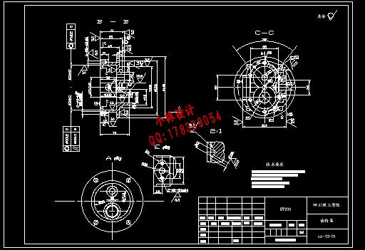
设计(论文)题目: 齿轮泵泵体工艺及加工Φ14、2-M8 孔夹具设计
1.毕业设计(论文)的主要内容及基本要求
1. 零件图一张, 毛坯图一张
2. 夹具装配图一份, 夹具零件图一套
3. 机械加工工艺卡一套, 主要工序工序卡一份
4. 设计说明书一份。
2.原始数据
零件图一张, 生产纲领10000件
3.指定查阅的主要参考文献及说明
1.《机械制造工艺手册》
2.《机械零件设计手册》
3.《夹具设计手册》
摘 要
在机械制造的机械加工、检验、装配、焊接和热处理等冷热工艺过程中,使用着大量的夹具,用以安装加工对象,使之占有正确的位置,以保证零件和产品的质量,并提高生产效率。
在机床上加工工件时,为了保证加工精度,必须正确安装工件,使其相对机床切削成形运动和刀具占有正确的位置,这一过程称为“定位”。为了不因受切削力、惯性力、重力等外力作用而破坏工件已定的正确位置,还必须对其施加一定的夹紧力,这一过程称为“夹紧”。定位和夹紧的全过程称为“安装”。在机床上用来完成工件安装任务的重要工艺装备,就是各类夹具中应用最为广泛的“机床夹具”。
机床夹具的种类很多,其中,使用范围最广的通用夹具,规格尺寸多已标准化,并且有专业的工厂进行生产。而广泛用于批量生产,专为某工件加工工序服务的专用夹具,则需要各制造厂根据工件加工工艺自行设计制造。因此,专用夹具的设计是一项重要生产准备工作,每一个从事加工工艺的工装设计人员,都应该掌握有关夹具设计的基础知识。
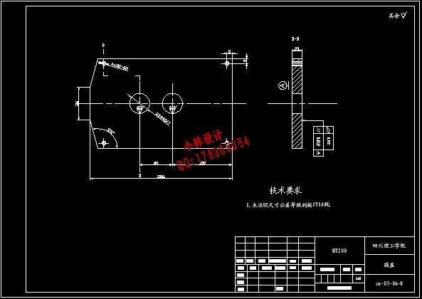
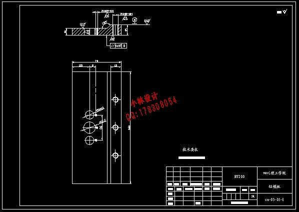
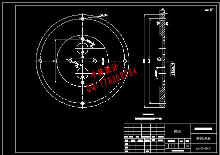
本设计的主要内容是设计钻床夹具,需要对齿轮泵端盖上的2个M8螺孔和1个 的孔进行钻削加工。文中介绍了工件在夹具体中的定位方式,定位元件与定位机构的选择,及夹紧机构的选择与设计。现代高效率的夹具大多采用机动夹紧,按力源分有气动、液压、气液联合、电传动及利用机床运动等对工件进行夹紧。这些方式具有夹紧动作快,夹紧力稳定,可减轻工人劳动强度等优点。本设计选用电动机作为夹紧的动力装置,运用机电传动控制回路来控制电动机的正反转,借以控制被加工工件在夹具体上的夹紧。此外,文中还对夹具进行了简单的精度分析与计算。
机械零件上往往都有各种不同用途和不同精度的孔需要加工。在机械加工中,孔的加工量所占比例较大,其中钻头、扩孔钻、铰刀等定尺寸刀具加工占相当多数。这时,除了要保证孔的尺寸精度外,还要达到孔的位置精度要求。在单件小批量生产中,用划线后找正孔轴线位置方法加工,更因钻头刚性差、易变形,因此生产效率低且精度差。在批量生产中一般都采用钻床夹具,钻床夹具又称钻模,通过钻套引导刀具进行加工可准确地确定刀具与工件之间的相对位置,是钻模的主要特点。钻削时,被加工孔的尺寸和精度主要由刀具本身的尺寸和精度来保证;而孔的位置精度则由钻套在夹具上相对于定位元件的位置精度来确定。因为通过钻套引导刀具进行加工,这就既可能提高刀具系统刚性,又能防止钻头引偏。
关键词:机械制造,通用夹具,专用夹具,钻床夹具,齿轮泵,电动机
ABSTRCT
At the machine manufacture machine-finishing, the examination,the assembly, the welding and the heat treatment and so on in the coldhot technological process, are using the massive jigs, with installsthe processing object, enable it to hold the correct position,guarantees the components and the product quality, and enhancementproduction efficiency.
Processes the work piece when the engine bed, in order to guaranteethe processing precision, must correctly install the work piece,causes its relative engine bed cutting forming movement and thecutting tool holds the correct position, this process is called "thelocalization". For because of Cutting force, inertial force , exogenic processand so on the gravity is not destroyed the work piece already thecorrect position which decides, but also must certainly exert to itclamps the strength, this process is called "clamps". Locates theentire process which and clamps to be called "the installment". Usesfor on the engine bed to complete the work piece to install the dutythe important craft equipment, is in each kind of jig widely applies"the engine bed jig".
Engine bed jig type very many, among, the use scope broadest generaljig, the specification size are many has standardized, and has thespecialty the factory to carry on the production. But widely uses inthe volume production, specially unit clamp which serves for some workpiece processing working procedure, then needs various factoriesindependently to design the manufacture according to the work pieceprocessing craft. Therefore, the unit clamp design is an importantproduction preparatory work, each is engaged in the processing craftthe work clothes design personnel, all should grasp the elementaryknowledge which the related jig designs.
This design main content designs the drilling machine jig, needs thecounter gear pumps on the end cover 2 M8 hole and 1 the holecarries on drills truncates the processing. In the article introducedthe work piece in clamps the concrete center the locate mode, locatesthe part and the detent mechanism choice, and clamps the organizationthe choice and the design. The modern high efficiency jig mostly usesmobile clamps, divides according to the strength source has airoperated, the hydraulic pressure, the gas fluid union, the electricitytransmission and so on carries on using the engine bed movement to thework piece clamps. These ways have clamp the movement quickly, clampsthe strength to be stable, may reduce merit and so on worker laborintensity. This design selects the power unit which the electric motorachievement clamps, the utilization mechanical and electricaltransmission control loop control motor the reverse, is processed inorder to the control the work piece in to clamp concrete on clamping.In addition, in the article has also carried on the simple precisionanalysis and the computation to the jig.
On the machine parts often all has each kind of different use and thedifferent precision hole needs to process. In the machine-finishing,the hole process load accounts for the proportion to be bigger, drillbit, Expanding drilling, Reamer and so on decides the size cutting toolprocessing to occupy quite most. By now, besides had to guarantee thehole the size precision, but also had to achieve the hole the positionprecision request. In the single unit small volume production, afterdraws a line adjusts the hole spool thread position method processing,because the drill bit rigidity bad, is easier to distort, thereforethe production efficiency low also the precision is bad. Generally alluses the drilling machine jig in the volume production, the drillingmachine jig calls 钻模, through drills the set of guidance cuttingtool to carry on the processing to be possible accurately to determinebetween the cutting tool and the work piece relative position, is钻模main characteristic. Drills when truncates, is processed thehole the size and the precision mainly by the cutting tool itself sizeand the precision guaranteed; But the hole position precision bydrills the set to be photogenic in the jig regarding locates the partthe position precision to determine. Because through drills the set ofguidance cutting tool to carry on the processing, this both possiblyenhances the cutting tool system rigidity, and can prevent the drillbit directs.
Keywords : machinery, common fixture, special fixture, drilling fixture, gear pumps, motors
目 录
中文摘要……………………………………………………………………………..Ⅰ
英文摘要……………………………………………………………………………..Ⅱ
第1章 绪论…………………………………………………………………………1
1.1机床夹具概述…………………………………………………………………...1
1.2机床夹具的发展趋势…………………………………………………………….1
第2章 工艺规程设计………………………………………………………………2
2.1 制定工艺路线…………………………………………………………………...2
2.1.1 工艺方案一………………………………………………………………...3
2.1.2 工艺方案二………………………………………………………………...3
2.1.3 最终工艺方案的确定……………………………………………………….4
2.2 机械加工余量、工序尺寸及毛坯尺寸的确定…………………………………...…5
2.2.1 机械加工余量、毛坯尺寸……………………………..……………………5
2.2.2 工序尺寸的确定………………………..……………..……………………5
2.3 切削用量计算………………………..……………..……………………...……7
第3章 专用夹具设计………………………………………………………………11
3.1 定位基准的选择………………………………………………………………11
3.2定位误差分析与计算……………………………………………………..……11
3.3 夹紧力的计算…………..………………………………………………..……11
3.4 夹具总体方案…………..………………………………………………..……13
3.5 传动装置的设计…………..…………….………………………………..……14
3.6 夹紧装置…………………..……………………………………………..……15
3.7钻套的选择……….………..……………………………………………..……16
3.8钻模板的设计………………..…….……………………………………..….…17
3.9夹具体的设计………………..…….…………………….………………..……20
3.10其他元件的设计…...………..…….…………………….………………..……21
3.11整机原理…...……………………..…….…………………….…………...………..……21
第四章 结论…………………………………………………………………….……22
参考文献….…………………………………………………………………………23
致谢……...………………………………………..…………………………………24
附卡1:机械加工工序卡….………………………………………………………25
附卡2:机械加工工艺过程卡1….………………………………………………26
附卡3:机械加工工艺过程卡2….………………………………………………27
|