 |
 |
|


|
设计名称 |
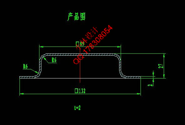
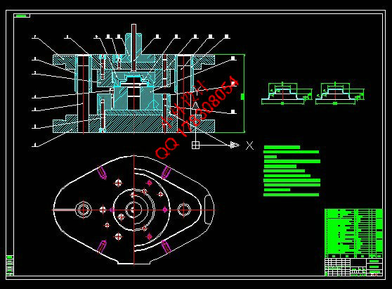
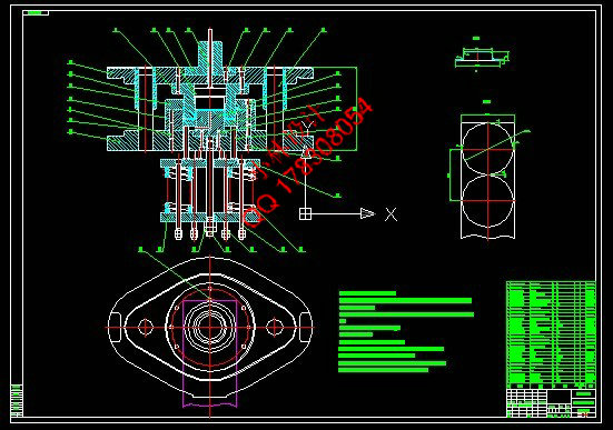
电喇叭底座冷冲压工艺及模具设计 |
 |
|
设计编号 |
Z293 | |
|
设计软件 |
AutoCAD, Word | |
|
包含内容 |
见右侧图片 | |
|
说明字数 |
27000字 | |
|
图纸数量 |
见右侧图片 | |
|
推荐指数 |
较高 | |
|
价格: |
价格优惠中 | |
|
整理日期 |
2013.9.26 | |
|
整理人 |
小林 | |
|
购买流程 |
<查看如何购买本站设计> |
|
设计简介 |
设计描述:
文档包括: CAD版本图纸,共20张
摘 要 ,模具技术已成为衡量一个国家产品制造水平高低的重要标志,决定着产品的质量、效益和新产品的
开发能力。
成零件(或半成品)的一种特殊工艺装备。 艺方案及模具结构方案,然后通过工艺设计计算,确定排样和裁板,计算冲压力和压力中心,初选压 力机,计算凸、凹模刃口尺寸和公差,最后设计选用零、部件,对压力机进行校核,绘制模具总装草 图,以及对模具主要零件的加工工艺规程进行编制。其中在结构设计中,主要对凸模、凹模、凸凹模
、定位零件、卸料与出件装置、模架、冲压设备、紧固件等进行了设计。 关键词:模具;冲裁件;凸模;凹模;凸凹模;
consistency, high production efficiency and low consumption and so on. Thus, die technology has become the measure of a country manufacturing an important indicator of the level determines the product quality, efficiency and new product development
capability. in the process of stamping, the material (metal or non-metallic) processing into parts
(orsemi-finished products) of a special technical equipment. production efficiency. according to the size of the design components, materials, mass production, etc., the first part of the process of analysis to determine the blanking process planning and die structure of the program, and then through the process design calculations, determine the nesting and cutting board, calculate the pressure and pressure washed centers, primary presses, computing convex and concave Die Cutting Edge dimensions and tolerances, the final design selection of parts and components, to press for checking, drawing die assembly drawings, as well as Mold processing technology of the main parts to the preparation procedures. In which the structural design, primarily to the punch and die, punch and die, positioning parts, unloading and out of pieces of
equipment, mold, pressing equipment, fasteners, etc. Key words: Die; Banking; Punch; Die; Main punch;
|
|
部分图纸 截图 |
     |
|
说明: |
如需了解本设计的具体详细信息请联系本站客服,说明看哪个设计(编号)哪个详细部分,我们将远程或截图给您观看. 机械毕业设计|论文 |

| [要求PR≥2,百度收录≥1000页;联系QQ:178308054] |
Powered by 小林机械资料商城 © 2013-2020 All Rights Reserved. 客服QQ:178308054
喜欢www.xiaolinbysj.com,请告诉你QQ上的5位好友,多谢您的支持!