|
设计描述:
文档包括:
word说明书一份,共66页,约28000字
任务书一份
开题报告一份
外文翻译一份
CAD版本图纸,共26张
摘 要
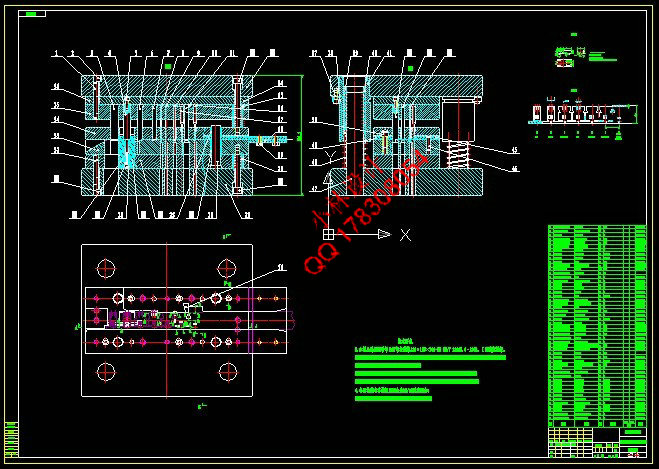
本模具采用切废料方式进行冲裁,故模具结构采用冲孔、导正、弯曲、切断的工序设计,排样采用单排横排排列。并采用正装方式设计模具结构,即凹模装在下模部分,凹模采用浮动方式,并装有内部小导柱。首先为了正确控制送料步距采用单侧侧刃定距,在主要位置采用导正销导正精确定位。由于料很薄,冲压速度较快,卸料采用弹性卸料结构,建议弹性材料采用弹簧。废料采用在凹模(下模)向下推出,产品自动向下落下。带料采用自动左右送料装置。
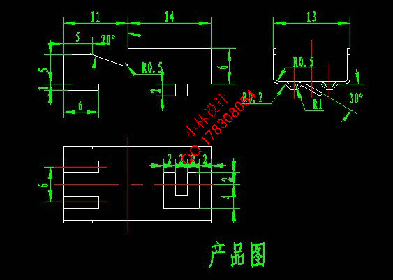
经过详细分析和计算最终排样方案为:侧刃切边,冲导正孔,冲2个非圆孔(废料),冲5个非圆孔(废料),冲2个非圆孔(废料),成形,中间向下弯曲,向上弯曲,最后切断。
关键词:多向固定支架;冲压工艺;排样;级进模
Abstract
The die used to cut waste by punching, punching die structure, guide, bending, cutting process design, arranged in a single row of horizontal nesting. And dress design the die structure die mounted on the lower die part, to die with floating and equipped with a small internal guide post. First order to properly control the feeding step away from the unilateral side of the blade fixed pitch in the main location pilots to precise positioning. The faster the material is thin, stamping, elastic Stripper Stripper structure, it is recommended that an elastic material with spring. Waste using the die (mold) launched down automatically fall down. With material automatically around feeding device.
After a detailed analysis and calculation of the final nesting program: the side edge trimming, pierced pilot hole, punch two non-circular hole (waste), red five non-round hole (waste), two non-circular hole punch (waste) , forming the intermediate bent downwardly bent upwardly, and finally cut.
Key words:Multi-directional mounting bracket;Stamping process;Nesting;Progressive die
目 录
摘 要 III
ABSTRACT IV
目 录 V
1 绪论 1
1.1 本课题的研究内容和意义 1
1.2 国内外发展状况 2
1.3本课题应达到的要求 3
2 冲压工艺设计 4
2.1 冲压件简介 4
2.2 冲压的工艺性分析 5
2.3 冲压工艺方案的确定 7
2.3.1 冲压模具类型 7
2.3.2 冲压工艺分析和计算 7
3 多向固定支架连续模设计 10
3.1 模具结构 10
3.2 确定其搭边值 10
3.3 确定排样图 11
3.3.1 送料步距与带料宽度 11
3.3.2 排样方案 13
3.4 材料利用率计算 13
3.5 凸、凹模等刃口尺寸的确定 14
3.5.1 侧刃凸、凹模刃口尺寸计算 14
3.5.2 导正孔凸、凹模刃口尺寸计算 14
3.5.3 梯形废料凸、凹模刃口尺寸计算 15
3.5.4 矩形废料Ⅰ凸、凹模刃口尺寸计算 17
3.5.5 矩形废料Ⅱ凸、凹模刃口尺寸计算 18
3.5.6 矩形废料Ⅲ凸、凹模刃口尺寸计算 19
3.5.7 矩形废料Ⅳ凸、凹模刃口尺寸计算 20
3.5.8 方形废料凸、凹模刃口尺寸计算 21
3.5.9 成形凸、凹模刃口尺寸计算 22
3.5.10 向下弯曲凸、凹模刃口尺寸计算 23
3.5.11 U型弯曲凸、凹模刃口尺寸计算 23
3.5.12 切断凸、凹模刃口尺寸计算 25
3.6 冲压力计算 26
3.6.1 冲孔部分冲压力 26
3.6.2 侧刃冲压力 27
3.6.3 成形部分冲压力 28
3.6.4 向下弯曲部分冲压力 28
3.6.5 U型弯曲部分冲压力 28
3.6.6 切断部分冲压力 29
3.6.7 总冲压力 29
3.7 压力机选用 29
3.8 压力中心计算 30
3.9 模具主要零部件的结构设计 31
3.9.1 凹模结构及设计 31
3.9.2 卸料板设计 33
3.9.3 凸模固定板设计 33
3.9.4 凸模垫板设计 34
3.9.5 凹模垫板设计 35
3.9.6 侧刃的结构设计 35
3.9.7 导正孔凸模结构设计 36
3.9.8 梯形凸模结构设计 37
3.9.9 矩形凸模Ⅰ结构设计 37
3.9.10 矩形凸模Ⅱ结构设计 38
3.9.11 矩形凸模Ⅲ结构设计 39
3.9.12 矩形凸模Ⅳ结构设计 39
3.9.13 方形凸模结构设计 40
3.9.14 成形凸模结构设计 41
3.9.15 向下弯曲凸模结构设计 41
3.9.16 U型弯曲凸模结构设计 42
3.9.17 切断凸模结构设计 43
3.9.18 前侧导板设计 43
3.9.19 后侧导板设计 44
3.9.20 U型弯曲凹模镶块设计 44
3.9.21 承料板设计 45
3.10 标准件确定 46
3.10.1 模架确定 46
3.10.2 上模螺钉确定 47
3.10.3 上模销确定 47
3.10.4 下模螺钉确定 47
3.10.5 下模销确定 47
3.10.6 卸料螺钉确定 47
3.10.7 卸料弹簧设计 47
3.10.8 凹模浮顶弹簧设计 48
3.10.9 凹模浮动卸料螺钉确定 48
3.10.10 弯曲弹顶弹簧设计 48
3.10.11 侧刃固定螺钉确定 49
3.10.12 U型弯曲凸模固定螺钉确定 49
3.10.13 小导柱确定 49
3.10.14 凹模上小导套确定 49
3.10.15 卸料板上小导套确定 49
3.10.16 导料板固定螺钉确定 49
3.10.17 导料板销确定 49
3.10.18 侧刃挡块设计 49
3.11 模具闭合高度、校验压力机 50
4 结论与展望 51
4.1结论 51
4.2不足之处及未来展望 51
致 谢 53
参考文献 54
| 


