|
设计简介 |
设计描述:
文档包括:
word说明书一份,共72页,约27000字
任务书一份
开题报告一份
外文翻译一份
CAD版本图纸,共22张
摘 要
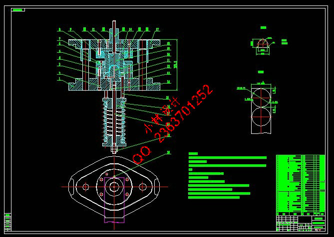
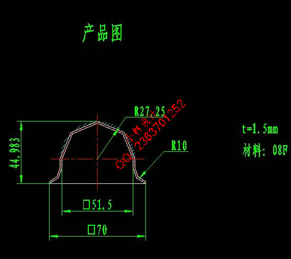
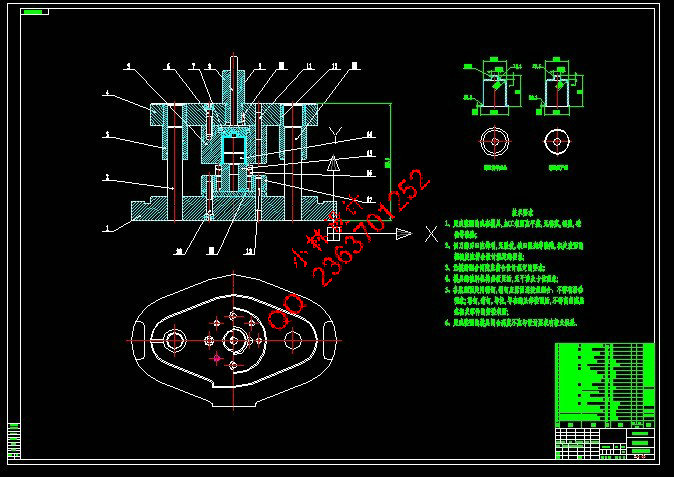
综合应用模具设计、冷冲压模具工艺、模具加工工艺学、工程图学等相关课程知识,对启动电机壳体采用多副模的工艺进行模具设计。本文在已完成开题报告的基础上,着重对复合模工作零件、定位零件、卸料推件零件及模架等主要零件的设计进行说明。在模具的设计中,按照小批量生产类型,对制件的冲压工艺进行分析,确定工艺方案,拟定排样方法,计算冲裁力,确定压力中心,计算凹凸模刃口尺寸及结构尺寸,得出模具闭合高度,选用标准件进行装配,最终画出模具总装图、三维模型及装配和主要零件加工工艺规程卡片。模具采用倒装结构,后侧导柱导套模架,导料销导料,弹顶式档料销档料,凸缘模柄,刚性推件及弹性卸料,在保证生产率的同时,尽可能的是模具、方便,且满足冲裁的要求。
关键词:启动电机壳体;冲压工艺;排样;模具结构;
Abstract
Comprehensive application of mold design, cold stamping mold process, mold processing technology, engineering, graphics and other related courses knowledge, start the motor housing using a plurality of mold process for mold design. In this paper, on the basis of complete opening report on the design of the main parts of the composite mold parts, positioning parts, discharge push parts and moldbase instructions. In mold design, in accordance with the type of small batch production parts stamping process analysis, to determine the process plan, intended nesting method to calculate the punching power, to determine the center of pressure, calculated the bump Edge size and structure size may the mold shut height, the choice of standard parts for assembly, and ultimately draw card of the mold assembly chart, the three-dimensional model and assembly and main parts process planning. Mold flip structure, the rear side of the guide pins and bushings mold, the stock guide pin guide material, playing the top-of-file material off of file material, the flange of the handle, rigid push pieces and elastic unloading, ensuring the productivity, although possible mold, convenient, and satisfying the requirements of the punched.
Key words: Start the motor housing; stamping process; nesting; guide pins and bushings;mold structure;
目 录
摘 要 III
Abstract IV
1 绪 论 1
1.1 课题研究的目的和意义 1
1.2 课题国内外研究概况 1
1.2.1 国外模具发展概况 1
1.2.2国内模具发展概况 2
1.3 课题研究的主要内容 2
2 冲压工艺设计 4
2.1 冲压件简介 4
2.2 冲压件的工艺性分析 7
2.3 冲压工艺方案的确定 8
2.4 冲压工艺计算 9
2.4.1 工件的毛坯尺寸计算 9
2.4.2 工序分析 10
2.4.3 拉深尺寸计算 10
2.4.5 整形 15
2.4.5 工序汇总 16
2.4.6 各工序尺寸公差的确定 16
2.5 产品所需模具 16
3 落料拉深模设计 20
3.1 模具结构 20
3.2 确定其搭边值 20
3.3 确定排样图 21
3.4 材料利用率计算 23
3.5 凸、凹模刃口尺寸的确定 24
3.5.1落料部份凸、凹模刃口尺寸的确定 24
3.5.2 拉深凸、凹模工作部分尺寸及其公差 25
3.6 落料拉深复合模冲压力 26
3.6.1 落料部分冲压力 26
3.6.2 拉深部分冲压力 27
3.6.3 落料拉深复合模总冲压力 28
3.7 压力机选用 28
3.8 压力中心计算 30
3.9 落料拉深模主要零部件的结构设计 30
3.9.1 落料凹模的结构设计 30
3.9.2 落料凸模的结构设计 32
3.9.3 落料卸料板设计 33
3.9.4 凸凹模(落料凸模)固定板设计 35
3.9.5 凸凹模(落料凸模)垫板设计 35
3.9.6 拉深凹模的结构设计 36
3.9.7 拉深凸模设计 37
3.9.8 落料凹模垫板设计 38
3.9.9 压边圈设计 39
3.9.10 推件块设计 40
3.10 标准件确定 41
3.10.1 模架确定 41
3.10.2 弹顶器的确定 41
3.10.3 上模螺钉确定 42
3.10.4 上模销确定 42
3.10.5 下模螺钉确定 42
3.10.6 下模销确定 43
3.10.7 模柄确定 43
3.10.8 模柄上固定螺钉的确定 43
3.10.9 推杆确定 43
3.10.10 拉深凸模上固定螺钉的确定 43
3.10.11 下模推杆的确定 43
3.10.12 条料定位零件的设计 44
3.11 模具闭合高度、校验压力机 44
4 切边模设计 45
4.1 模具结构 45
4.2 切边凸、凹模刃口尺寸的计算 45
4.3 切边模冲压力 47
4.4 压力机选用 47
4.5 压力中心计算 48
4.6 切边模主要零部件的结构设计 48
4.6.1 切边凹模的结构设计 48
4.6.2 切边凸模的结构设计 50
4.6.3 切边凸模固定板设计 50
4.6.4 切边凸模垫板设计 51
4.6.5 定位柱设计 52
4.6.6 推件块设计 53
4.7 标准件确定 53
4.7.1 模架确定 53
4.7.2 上模螺钉确定 54
4.7.3 上模销确定 54
4.7.4 下模螺钉确定 54
4.7.5 下模销确定 54
4.7.6 模柄确定 54
4.7.7 圆废料切刀确定 55
4.7.8 推杆确定 55
4.7.9 模柄紧定螺钉的确定 56
4.8 模具闭合高度、校验压力机 56
5 结论与展望 57
5.1 结论 57
5.2 不足之处及未来展望 57
致 谢 58
参考文献 59
|


