|
设计简介 |
设计描述:
文档包括:
word说明书一份,共66页,约33000字
任务书一份
开题报告一份
外文翻译一份
CAD版本图纸,共21张
摘 要
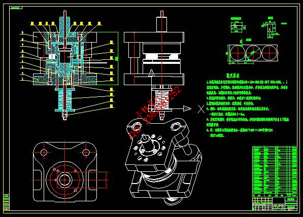
冲压生产是一种先进的金属加工方法。它是利用模具和冲压设备对板材金属进行加工,通过冲压生产可以获得所属要的零件形状和尺寸。本课题是轴端盖罩零件的冲压模具的设计,本产品外形是圆形,根据设计零件的尺寸、材料、生产批量等要求,分析零件的工艺性,根据工件的形状和批量,对模寿命有一定要求,故采用有废料排样方法,确定冲裁工艺路线方案,从而设计一套复合模具,本次模具选取的是简单的二次拉深工艺模,综合考虑冲压件的形状特点、尺寸大小、精度要求及冲压设备与制模条件,操作方便与安全。模具1:落料拉深复合模和模具2:第2次拉深模,第一副模具是落料拉深复合模,卸料采用弹性(弹簧)卸料结构,工件采用推件块刚性推出,推出机构装在上模部份,压边装置装在下模部份,采用弹性(弹簧)结构,同时也起向上推件作用。条料采用手动送料装置,样时工件之间以及工件与条料侧边之间留下的余料叫做搭边。搭边的作用是补偿定位误差,保证冲出合格的工件。还可以使条料有一定的刚度,便于送进。由于第一副模具是落料拉深复合模,只需考虑落料的排样,故采用单排直排方式。
采用单排直排方式在保证工件的尺寸和形状位置精度要求的同时,尽量的提高材料的利用率和生产效率。随着计算机技术的不断发展,采用CAD/CAE/CAM一体化技术可以准确、快速的完成模具设计制造。本文主要是介绍说明了轴端盖罩零件成形的各个工序及其模具的设计及尺寸计算,在结构设计的同时,对主要零件的设计和装配要求技术进行了分析。设计时考虑到模具设计合理、简单,便于制造和修模,有利于缩短模具生产制造周期,降低成本。
关键词:盖罩零件;冲压工艺;复合模;模具设计
Abstract
Stamping production is a kind of advanced metal processing method. It is the use of mould and stamping equipment to carry on the processing of sheet metal. Through stamping production, we can get the shape and size of the parts which we need. This topic is about the design of the stamping mould for the shaft end cover parts. According to requirements of part size, material, production batch, etc. we should analyze the manufacturability of parts, and determine a medium manufacture route to design a set of compound mould. The mould selection of deep drawing technology is a simple quadratic model, considering the shape of the stamping characteristics, size, accuracy and stamping equipment and molding conditions, convenient operation and safety. Mold 1: blanking deep drawing die and mould 2: the second drawing die, first deputy die blanking, deep drawing composite modulus is discharging structure of elastic unloading (spring), artifacts using push a piece of rigid, launch mechanism mounted on the upper die, blank holder device installed in mold parts, the structure of elastic (spring), and push up a role as well. Manual feeding device for the strip material, article sample between artifacts and artifact and between the material side of excess stock is called on. On the position error compensation, ensure rushed out of the qualified parts. Can also make the strip material has certain rigidity, easy to into. As the first vice mould is blanking, deep drawing composite modulus, just consider the layout of blanking, the single straight line method is adopted.We not only should ensure the size and shape of the workpiece position accuracy requirements, but also try to improve material utilization and production efficiency. Along with the unceasing development of computer technology, it is accurate and fast to use the integration technology of CAD/CAE/CAM to complete the die designing and manufacturing. This paper mainly illustrates the shaft end cover parts forming process and the mold of each design and size calculation, the structural design of the main parts, meanwhile, the design and assembly required technologies are analyzed. When designing, we consider that the die structure should be reasonable and simple to manufacture and repair and advantageous to reduce the manufacturing cycle of die production and the costs.
Keywords: shaft end cover parts; Stamping process; Composite modulus; Die design
目 录
摘 要 III
Abstract IV
目 录 V
1 绪论 1
1.1 本课题的研究内容和意义 1
1.2 国内外的发展概况 3
1.3 本课题应达到的要求 5
2 冲压工艺设计 6
2.1 冲压件简介 6
2.2 冲压件的工艺性分析 8
2.3 冲压工艺方案的确定 10
2.4 冲压工艺计算 11
2.4.1 工件的毛坯尺寸计算 11
2.4.2 工序分析 12
2.4.3 拉深尺寸计算 13
2.4.4 工序汇总 17
2.4.5 各工序尺寸公差的确定 17
2.5 产品所需模具 17
3 落料拉深模设计 20
3.1 模具结构 20
3.2 确定其搭边值 20
3.3 确定排样图 21
3.4 材料利用率计算 22
3.5 凸、凹模刃口尺寸的确定 22
3.5.1落料部份凸、凹模刃口尺寸的确定 22
3.5.2 拉深凸、凹模工作部分尺寸及其公差 24
3.6 落料拉深复合模冲压力 25
3.6.1 落料部分冲压力 25
3.6.2 拉深部分冲压力 26
3.6.3 落料拉深复合模总冲压力 27
3.7 压力机选用 27
3.8 压力中心计算 29
3.9 落料拉深模主要零部件的结构设计 29
3.9.1 落料凹模的结构设计 29
3.9.2 落料凸模的结构设计 31
3.9.3 条料定位零件的设计 31
3.9.4 落料卸料板设计 32
3.9.5 凸凹模(落料凸模)固定板设计 32
3.9.6 凸凹模(落料凸模)垫板设计 33
3.9.7 拉深凹模的结构设计 34
3.9.8 拉深凸模设计 35
3.9.9 压边圈设计 35
3.9.10 推件块设计 36
3.10 标准件确定 36
3.10.1 模架确定 36
3.10.2 弹性组件设计 37
3.10.3 卸料螺钉确定 38
3.10.4 上模螺钉确定 38
3.10.5 上模销确定 38
3.10.6 下模螺钉确定 38
3.10.7 下模销确定 38
3.10.8 模柄确定 39
3.10.9 推杆确定 39
3.10.10 模柄上固定螺钉的确定 39
3.10.11 拉深凸模上固定螺钉的确定 39
3.10.12 下模推杆的确定 39
3.10.13 弹顶器的确定 39
3.11 模具闭合高度、校验压力机 40
4 二次拉深模具设计 41
4.1 确定模具的结构形式 41
4.1.1 正、倒装结构的选择 41
4.1.2 工件定位方式选择 42
4.1.3 推件方式的选择 42
4.1.4 压边方式的选择 42
4.1.5 导向方式的选择 42
4.2 拉深凸、凹模工作部分尺寸的确定 42
4.2.1 拉深凸、凹模刃口尺寸确定原则 42
4.2.2 拉深凸、凹模工作部分尺寸和公差 42
4.3 二次拉深模的冲压力计算 43
4.3.1 拉深力 43
4.3.2 压边力 43
4.3.3 拉深部分总冲压力 44
4.4 压力机选用 44
4.5 压力中心计算 44
4.6 拉深模主要零部件的结构设计 44
4.6.1 拉深凹模的结构设计 44
4.6.2 拉深凸模设计 45
4.6.3 压边定位圈设计 46
4.6.4 推件块设计 47
4.6.5 限位装置设计 47
4.7 标准件确定 48
4.7.1 模架确定 48
4.7.2 上模螺钉确定 48
4.7.3 上模销确定 48
4.7.4 模柄确定 49
4.7.5 模柄防转紧定螺钉的确定 49
4.7.6 带螺纹推杆的确定 49
4.7.7 带螺纹推杆螺母的确定 49
4.7.8 弹性元件设计 49
4.7.9 弹顶器的确定 50
4.7.10 拉深凸模上固定螺钉的确定 50
4.7.11 带肩推杆的确定 50
4.8 模具闭合高度、校验压力机 50
5 结论与展望 52
5.1 结论 52
5.2 不足之处及未来展望 52
致 谢 53
参考文献 54
|