|
设计简介 |
设计描述:
文档包括:
word说明书一份,共44页,约12000字
任务书一份
开题报告一份
外文翻译一份
CAD版本图纸,共20张
摘 要
近年来,随着我国汽车、家电工业的高速发展,对于模具工业,尤其是冷冲模具提出了越来越高、越来越科学的要求。
多工位级进模是在普通级进模的基础上发展起来的一种高精度、高效率、长寿命的模具,是技术密集型模具的重要代表,是冲模发展方向之一。一副级进模在一次冲压动作中可在模具不同工位进行不同的冲压操作。这些在通过模具的带料上同时进行的冲压动作制造出零件。每个工位可进行一个或多个操作,但要生产出完整的零件条料必须经过每一个工位。而零件依靠零件之间的载体输送到各个工位,并在最后一个工位进行切除。
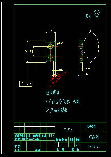
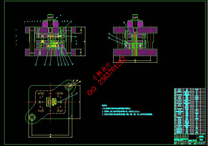
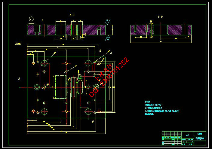
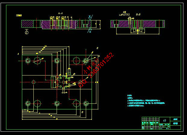
本设计对嵌件板进行的级进模设计,通过对级进模冲压成型的工作原理,以及根据级进模定位零件的特征对铁片进行加工。同时利用Auto CAD 软件对制件进行设计绘图。明确了设计思路,确定了冲压成型工艺过程并对各个具体部分进行了详细的计算。并绘制了模具的装配图和零件图。
关键词:级进模;冲压;AutoCAD
Abstract
In recent years, as China's automobile, hose-appliance industry, the rapid development of the mold industry, especially Die with higher and higher, more scientific requirements.
Multi-position into modules are o-level into mode in the developed on the basis of a kind of high precision, high efficiency, long life mold, is an important representative of technology-intensive mould, is one of stamping development direction.A progressive die performs a series of fundamental sheet metal operations at two or more stations in the die during each press stroke. These simultaneous operations produce a part from a strip of material that moves through the die. Each working station performs one or more die operations, but the strip must move from the first station through each succeeding station to produce a complete part. Carriers, consisting of one or more strips of material left between the parts, provide movement of the parts from one die station to the next. These carrier strips are separated from the parts in the last die station.
The design of the Insert plate of the progressive die design, through the progressive die stamping works, and locate parts progressive die based on the characteristics of the Iron tablets for processing. While using Auto CAD software to design parts drawing. Clear design ideas, determine the process of stamping and forming part of the various specific details of the calculation.And the mapping of the mold assembly and part drawings.
Key words: progressive die; press; AutoCAD
目 录
摘 要 III
Abstract IV
目 录 V
1 绪论 1
1.1 本课题的研究意义 1
1.2 我国级进模的发展现状 1
2 冲压工件的工艺分析及排样图设计 2
2.1 工艺分析 2
2.2 排样图设计 2
2.3 压力中心的计算 4
3 设计过程中的主要计算 5
3.1 步距及条料标称宽度的计算 5
3.2 冲 孔 5
3.2.1 冲裁力,卸料力,推件力计算 5
3.2.2 冲裁间隙及凹模,凸模刃口尺寸公差计算 6
3.3 以两个 的孔导正切边 6
3.3.1 冲裁力,卸料力,推件力计算 6
3.3.2 冲裁间隙及凹模,凸模刃口尺寸公差计算 7
3.4 以导正孔导正压锥角 8
3.4.1 压印力,卸料力,推件力计算 8
3.4.2 凹模,凸模刃口尺寸公差计算 9
3.5 冲外型、落料 9
3.5.1 冲裁力,卸料力,推件力计算 9
3.5.2 冲裁间隙及凹模,凸模刃口尺寸公差计算 9
3.6 侧刃 10
3.6.1 冲裁力,卸料力,推件力计算 10
3.7 导正销尺寸 11
3.7.1 导正销工作部分直径 11
3.8 空位 11
4 模具结构总体设计 12
5 模具主要零件设计 13
5.1 定位装置 13
5.2 卸料装置: 13
5.2.1 弹性元件 13
5.2.2 卸料板 15
5.2.3 卸料螺钉 15
5.3 固定机构的设计 15
5.3.1 板类零件的定位连接 15
5.4 凸,凹模的设计 16
5.4.1 凹模 16
5.4.2 凸模 18
5.5 固定零件 24
5.5.1 模柄 24
5.5.2 固定板与垫板 24
5.5.3 模架 24
5.6 导向零件 24
5.7 压力机的选择 25
6 模具材料的选取 26
6.1 凸凹模材料的选择 26
6.2 其它主要零件材料的选取见下表 26
设计总结 27
致谢 28
参考文献 29
|


