|
设计简介 |
设计描述:
文档包括:
WORD版设计说明书1份,共49页,约17000字左右
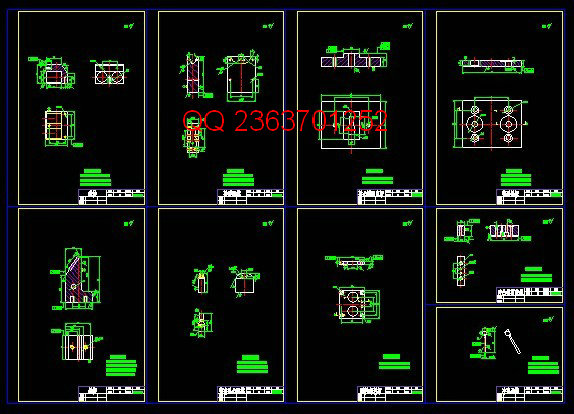
CAD版本图纸,共21张
摘 要
油斗是用于机电设备仪器上的零件,主要是利用其进行储油,属于冲压拉深件,一般所使用的材料是铝,材料较薄,不超过0.5mm。本次设计主要是以油斗为设计对象,制定合理的冲压工艺方案并设计模具的结构。由于工件尺寸较小、形状复杂、内外形尺寸相差很小,并且生产量较大,故选择落料拉深复合模和整形冲孔复合模加工。复合模生产能提高生产率、降低生产成本、提高产品质量和实现自动化。该模具采用落料、拉深、冲孔成形,先冲出油斗制件的展开外形、然后拉深、最后整形、冲孔完成工件的整个加工。本模具共四道工序,其中涉及到拉深、落料、整形和冲孔,模具相对复杂,为了保证侧孔的精度,还设计了侧冲机构;送料方式采用手动送料,在首套模具中设计了固定挡料销,保证了送料步距的准确。
关键词:油斗;冲压;拉深;复合模;侧壁冲孔
ABSTRACT
Oil bucket is used in electromechanical equipment instrument. As a stamping press product, its thickness is no less than 0.5mm, the material of which used is aluminum. The oil bucket is the main object of this design, the main purpose of which is to constitute a reasonable stamping technology plan and the die’s construction. Since the shape of the product is small and complicated, and the difference of the dimensions between the inside and outside parts is little, and the production is rather big, so we choose blanking composite die and deep hole processing plastic composite die to produce. Composite die can improve productivity and reduce production cost, improve product quality and realize automation. The die adopts blanking, deep drawing, punch forming,First to blank the displayed shape of oil bucket,then to deep, plastic and complete the workpiece finally. The die has four working procedures,including deep, blanking, plastic and punching.Cause the die is relatively complicated, to design side blunt institutions in order to ensure the precision of side holes; to adopt manual feeding and to design a fixed block material sales in initial die in order to guarantee the precise feeding steps.
Key words: Oil Bucket, Stamping, Deep, Composite Die, Side Punching
目 录
摘要 ………………………………………………………………………………………Ⅰ
Abstract …………………………………………………………………………………Ⅱ
第 1章 绪论……………………………………………………………………………1
1.1选题的背景…………………………………………………………………………1
1.2研究状况……………………………………………………………………………1
1.3相关领域的发展……………………………………………………………………1
1.3.1 冲压技术发展的特征 ………………………………………………………2
1.3.2 先进成型技术的发展 ………………………………………………………2
1.3.3 冲压成型技术的发展趋势 …………………………………………………2
1.4选题研究方法………………………………………………………………………3
1.5预期结果和意义……………………………………………………………………3
第 2 章 零件拉深工艺性分析………………………………………………………4
2.1制件的工艺分析 …………………………………………………………………4
2.2在设计中需要着重解决的问题 …………………………………………………5
2.3本章小结 …………………………………………………………………………5
第 3 章 分析比较和确定工艺方案…………………………………………………6
3.1方案的比较………………………………………………………………………6
3.2模具结构形式的选择……………………………………………………………7
3.2.1模具的导向装置……………………………………………………………7
3.2.2模具的卸料装置…………………………………………………………7
3.3本章小结…………………………………………………………………………7
第 4 章 拉深件的工艺参数计算…………………………………………………8
4.1拉深件毛坯尺寸的计算…………………………………………………………8
4.2拉深件毛坯尺寸的计算…………………………………………………………10
4.3排样图的确定……………………………………………………………………10
4.3.1送料步距的计算…………………………………………………………11
4.3.2条料宽度计算……………………………………………………………11
4.3.3拉深模送料方式…………………………………………………………12
4.3.4承料板的尺寸……………………………………………………………12
4.4本章小结…………………………………………………………………………13
第 5 章 力的计算及压力机的选择………………………………………………14
5.1冲裁力的计算……………………………………………………………………14
5.1.1拉深力的计算……………………………………………………………15
5.1.2落料力、冲孔力、整形力的计算…………………………………………15
5.1.3压边力的计算……………………………………………………………16
5.1.4卸料力、推件力、总冲裁力的计算………………………………………17
5.2模具压力中心的确定……………………………………………………………18
5.3压力机的选择……………………………………………………………………18
5.4本章小结…………………………………………………………………………18
第 6 章 凸凹模尺寸计算……………………………………………………………19
6.1落料、侧壁冲孔的凸凹模计算……………………………………………………19
6.1.1侧壁冲孔的凸凹模计算…………………………………………………19
6.1.2冲油斗展开外形的凸凹模计算…………………………………………20
6.2拉深部分的凸凹模计算与整形凸凹模尺寸……………………………………22
6.2.1拉深部分的凸凹模计算…………………………………………………22
6.2.2整形的凸凹模计算………………………………………………………25
6.3模具整体结构的初步确定………………………………………………………27
6.4本章小结…………………………………………………………………………28
第 7 章 模板的选择…………………………………………………………………30
7.1凹模板周界尺寸计算……………………………………………………………30
7.2模架的选择………………………………………………………………………30
7.2.1上模座的选择……………………………………………………………31
7.2.2下模座的选择……………………………………………………………31
7.2.3导柱导套的选择…………………………………………………………32
7.3凹模板的选择……………………………………………………………………33
7.4垫板的选择………………………………………………………………………33
7.5固定板的选择……………………………………………………………………34
7.6卸料板的选择……………………………………………………………………34
7.7复位弹簧的选择…………………………………………………………………36
7.8模柄的选择………………………………………………………………………36
7.9本章小结…………………………………………………………………………37
第 8 章 模具各零件部分的设计与计算…………………………………………38
8.1拉深部分凸模设计………………………………………………………………38
8.2冲孔部分凸模设计………………………………………………………………38
8.3落料、拉深、整形、冲孔凹模设计…………………………………………………39
8.4侧冲机构的设计与计算…………………………………………………………42
8.4.1斜楔与滑块的设计………………………………………………………42
8.4.2弹性复位机构……………………………………………………………44
8.5模具的闭合高度校核……………………………………………………………44
8.6本章小结…………………………………………………………………………46
结论………………………………………………………………………………………46
参考文献…………………………………………………………………………………47
致谢………………………………………………………………………………………48
|


