|
设计简介 |
计描述:
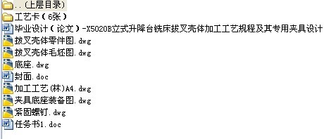
文档包括:
Word版说明书一份,共37页,约18000字
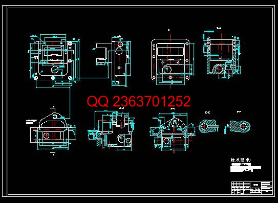
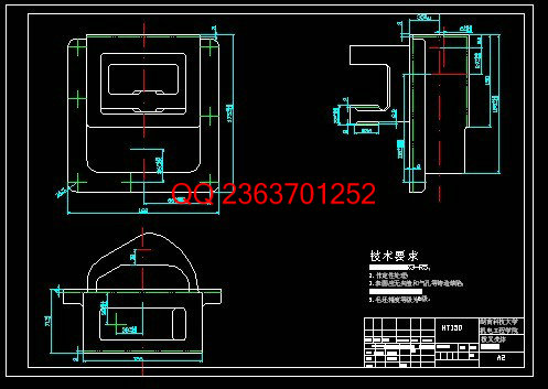
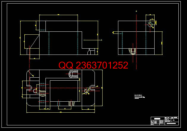
CAD版本图纸,共6张:
加工工艺规程制订及其工序专用夹具的设计
X5020B立式升降台铣床拨叉壳体
摘 要:本次设计抛开以往的设计思想,浓缩了一个新方案。通过对X5020B立式升降台铣床拨叉壳体
两种加工工艺路线的比较分析,选定前者。该方案是以三个面作为基准,实现基准统一原则,简化了随行
夹具的设计,从而在保证所要求的质量和劳动生产率指标的前提下降低了生产成本。而且专用夹具的
设计严格按照先收集和研究有关资料,再确定夹具的结构方案,然后绘制夹具总图,最后确定并标注
有关尺寸及技术条件的步骤进行,充分体现了提高劳动生产率、保证加工质量、降低劳动强度的原则,
论文中将以详细的计算和说明证明这一说法。
关键词:拨叉壳体;加工工艺;夹具
Abstract:This design gets rid of the traditional thoughts, and tries a new method. Through design techinics regulations for
machining of the X5020B vertical lift platform mill machine .There are two schemes to select. At last ,we choose the former after analyzing the structure and the efficiency of the part. In this scheme, we can get to the fiducial unity and simplify special clamp designing base on three planes,so that cut down the product cost with making sure the demand of the quality and labor productivity. Also, according to getting together and studying much datum, I design the special clamp for two holes .Firstly, decide the scheme for the structure of clamp ;Secondly, draw the collectivity drawing, At last, label the joint dimensions., which enhances the work productivity, and makes certain the product quality, and reduce the labor intensity .In the paper, we layout the detailed calculate and explation.
Keyword*****tract fork shell;techinics regulations;clamp
目 录
摘要
前言
1 毕业设计任务书----------------------------------------------------------------------------------4
2 零件的结构功用分析----------------------------------------------------------------------------4
3 材料及毛坯种类的选用-------------------------------------------------------------------------5
4 基面的选择----------------------------------------------------------------------------------------7
5 工艺路线的制订----------------------------------------------------------------------------------8
6 确定机械加工余量、工序尺寸及公差-------------------------------------------------------10
7 确定切削用量、工时定额及切削力和切削功率-------------------------------------------21
8 专用夹具设计
8.1 X5020B工件技术分析-----------------------------------------------------------------22
8.2 工序内容总体方案的拟定-------------------------------------------------------------24
8.3 定位方案的拟定-------------------------------------------------------------------------25
8.4 夹紧力的计算和夹紧结构-------------------------------------------------------------27
8.5 定位误差分析及夹具精度分析-------------------------------------------------------29
8.6 镗模装配总图的绘制-------------------------------------------------------------------30
8.7 零件图的绘制----------------------------------------------------------------------------31
8.8 部分典型结构及数据-------------------------------------------------------------------32
9 结论
10 致谢
11 参考文献
12 注释
13 附录
|


