|
设计简介 |
设计描述:
文档包括:
word说明书一份,共46页,约23000字
任务书一份
开题报告一份
外文翻译一份
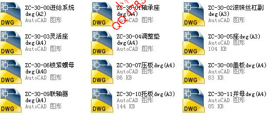
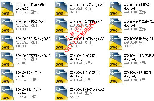
CAD版本图纸,共33张
摘 要
组合机床是一种高效率专用机床,有一定的使用条件,不是在所有情况下都可以收到良好的经济效益,在确定设计机床前,需要进行具体的经济技术论证。加工同一个产品的零件,通常会有很多种工艺方法,不同的方法会有不同的经济效益,影响技术经济的成分有很多,有时技术指标先进的方发,经济指标不一定先进,因此,需要对技术、经济指标作综合评估,综合多数的意见,选出优化方法进行经济效果评估,如果满意即可决定采用哪种方法。
本课题设计的是双端面孔加工组合机床。其来源于惠发特精密机械有限公司。在设计中:通过研究被加工零件的特点,对相关数据进行计算,对相关部件进行选择,从而确定机床的整体布局。并绘制出被加工示意图,加工零件工序图,机床联系尺寸图和生产率计算卡。在此条件上拟定了主轴箱的传动路线,设计了轴的结构,进行了皮带轮及轴等相关零件的强度,刚度校核,并绘制出主轴箱总装图和相关零件图。该机床对零件的两端孔同时进行加工,加工的工艺性好,工件装夹方便。采用滚珠丝杠导轨实现刀具进给。工件采用V形块定位,液压夹紧,一次装夹完成不止保证了孔的加工精度,而且还提升了加工效率,降低了工人的劳动强度。
关键词: 组合机床;双端面孔加工;液压夹紧
Abstract
Combination machine tools is an efficient special machine tool, has the certain conditions of use, can not in all cases received good economic benefits, before the design of machine tool is determined, specific economic and technical argument is required. Processing parts of the same product, usually there are many kinds of processing methods, different methods have different economic efficiency, influence the composition of the technical and economic has a lot of, sometimes technical indicators advanced party, advanced economic indicator does not necessarily, therefore, need to make a comprehensive evaluation of technical and economic indicators, comprehensive the opinions of the majority, to select the optimal method for economic evaluation, if satisfaction can be decided to use which method.
This topic design is of double end face processing combination machine tools. It is derived from HuiFa precision machinery co., LTD. In design: by studying the characteristics of the processed parts and the related data to calculate, to choose of related parts, to determine the overall layout of machine tool. And map out the process diagram, process diagram, processing parts machine tool contact card size chart and productivity calculation. Conditions on which to formulate the spindle box of transmission route, design the structure of the shaft, the pulley and shaft parts related to strength, stiffness, and draw out the spindle box assembly diagram and related detail drawings. The machine tool and parts at both ends of the hole processing, processing of good manufacturability, workpiece clamping and convenient. With ball screw feed ? guide implementation tools.
Key words: combination machine; double-face processing; the hydraulic clamping
目录
摘要...............................................................................................................................................III ABSTRACT...................................................................................................................................IV
目录.................................................................................................................................................V
1 绪论 1
1.1 本课题的研究内容和意义 1
1.2 国内外的发展概况 1
1.3 本课题应达到的要求 1
2 对总体设计的理解 3
2.1 机床的主要用途 3
2.2 机床的主要部件 3
2.3总体设计工艺方案的制定 3
2.3.1工序 3
2.3.2安装 4
2.3.3 拟订加工工艺路线 5
2.3.4 两种加工路线的比较 5
2.3.5 刀具与夹具的比较 6
2.3.6 工序的集中与分散 7
2.3.7 确定加工工艺路线 7
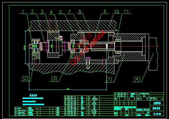
3 进给系统设计 8
3.1 确定传动方式 8
3.2 联轴器的选用 8
3.3 导轨形式的确定(选用和载荷计算) 8
3.3.1 选用 8
3.3.2 载荷计算 9
3.4 滚珠丝杆的机械特性的设计计算 9
3.5 滚珠丝杆副的选用 13
3.6 滚珠丝杆的验算 13
3.7 步进电机的选用 14
3.8 传动系统的结构设计 17
3.8.1 螺母 17
3.8.2 活灵座 17
3.8.4 拖板 22
3.8.5 丝杆夹具 23
3.9 进给系统图 24
4 夹具设计 25
4.1 被加工零件的加工要求 25
4.2 夹具设计的主要依据 26
4.2.1 被加工零件的加工精度和加工工序 27
4.2.2 被加工零件特点 27
4.2.3 零件的生产批量 27
4.3 工件的定位方案确定 28
4.3.1 加工示意图的作用和内容 28
4.3.2 加工示意图的画法及注意事项 28
4.3.3 选择刀具,工具,导向装置并标注其相关位置及尺寸 28
4.4 工件夹紧方案确定 29
4.4.1 夹紧方向 29
4.4.2夹紧部件 30
4. 5 定位元件,夹紧元件的设计 35
4.5.1定位元件的设计 35
4.5.2 夹紧元件设计 35
4.6 夹紧力计算 36
4.7 夹紧油缸设计 36
4.7.1 液压缸的载荷组成与计算 37
4.7.2 初选系统工作压力 39
4.7.3 液压缸的主要结构尺寸 41
4.7.4 油缸密封 41
4.8 夹具体及其他零件设计 41
4.8.1 外形简图 41
4.8.2 材料选择 42
4.9 夹具的安装与调整 43
4.9.1 安装 43
4.9.2 调整 43
4.9.3 夹具的可调节性 43
5 总结与展望 44
致 谢 45
参考文献 46
|