|
设计简介 |
设计描述:
文档包括:
word说明书一份,共51页,约21000字
任务书一份
开题报告一份
外文翻译一份
CAD版本图纸,共7张
摘 要
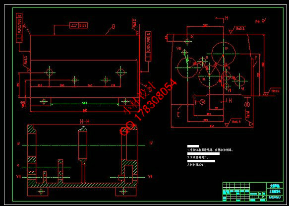
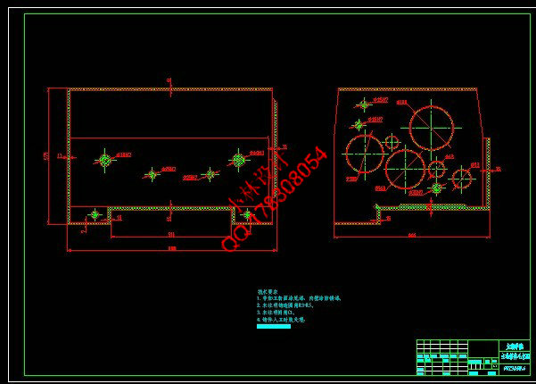
本文是对箱体零件三维造型及零件的机械加工工艺路线进行设计,并按照加工工序的要求进行了夹具设计。三维造型主要表达了零件的造型过程,并可根据零件三维图样自动生成零件的数控加工程序。
主轴箱作为箱体类零件,其主要加工表面是平面及孔。其加工路线长,加工时间多,加工成本较高,零件的加工精度要求也较高。按照机械加工工艺要求,遵循先面后孔的原则,并将孔与平面的加工明确划分成粗加工和精加工阶段以保证加工精度。基准选择以底面作为粗基准,以底面与两个工艺孔作为精基准,确定了其加工的工艺路线和加工中所需要的各种工艺参数。
在零件的夹具设计中,主要是根据零件加工工序要求,分析应限的自由度数,进而根据零件的表面特征选定定位元件,再分析所选定位元件能否限定应限自由度。确定了定位元件后还需要选择夹紧元件,最后就是确定专用夹具的结构形式。
关键词 主轴箱;加工工艺;工序;专用夹具
Abstract
This article is to the body parts 3 d modelling and parts machining process route design, and according to the requirements of machining process for fixture design. 3 d modelling mainly expressed the moulding process of the parts, and can according to the parts 3 d drawings of nc machining program automatically generate parts.
The main spindle box, a box body parts, the main processing surface is flat and hole. Its processing route, long processing time, processing cost is higher, the machining precision of parts request also is higher. According to the machining process requirement, follow the principle of surface hole after first, and will be in the plane of the hole and processing into rough machining and finish machining stage to ensure the machining accuracy. Crude benchmark, the benchmark choice on bottom as the bottom with two hole as a benchmark, to determine the processing technology and processing required in the various process parameters.
In parts of fixture design, mainly according to the parts processing process requirements, the analysis should limit the freedom degree, and according to the surface features of parts positioning element selected, then analysis the selected components can limit should be the limit of degrees of freedom. Determine the positioning components also need to select after clamping device, the structure of special fixture is determined in the end.
Key words spindle box; Processing technology; Process; Special fixture.
目录
摘 要 III
Abstract IV
目录 V
1 绪论 1
1.1本课题的研究内容和意义 1
1.2国内外的发展概况 1
1.3本课题应达到的要求 2
2 零件的造型 3
3 零件的分析 6
3.1零件的作用 6
3.2 零件的工艺分析 7
3.2.1零件图样分析 7
3.2.2 工艺分析 8
4 工艺规程设计 10
4.1 确定毛坯的制造形式 10
4.2 定位基准的选择 11
4.2.1 粗基准的选择 11
4.2.2 精基准的选择 12
4.3 拟定工艺路线 13
4.3.1 划分加工阶段 13
4.3.2 安排加工顺序 13
4.3.3 拟定加工工艺路线 14
4.4 机械加工余量、工序尺寸及毛坯尺寸的确定 16
4.5 确定切削用量及工时定额 18
5 专用夹具设计 33
5.1 问题的指出 33
5.1.1 机床夹具的作用 33
5.1.2 铣床夹具的主要类型及结构形式 33
5.1.3 机床夹具的组成 34
5.2 夹具设计 34
5.2.1夹具体设计 34
5.2.2 定位基准的选择 34
5.2.3 定位方案和元件设计 34
5.2.4 定位误差的计算 35
5.2.5 铣削切削力计算 35
5.2.6 夹紧机构的设计 36
5.2.7 对刀装置 37
6 结论与展望 38
6.1结论 38
6.2不足之处及未来展望 38
设计小结 39
致谢 40
参考文献 41
|


