|
设计简介 |
设计描述:
文档包括:
word说明书一份,共44页,约15000字
任务书一份
开题报告一份
外文翻译一份
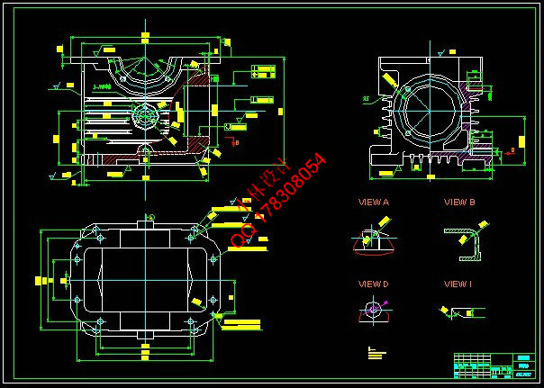
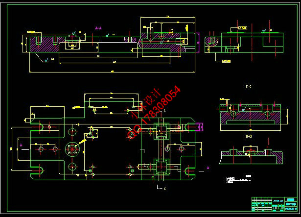
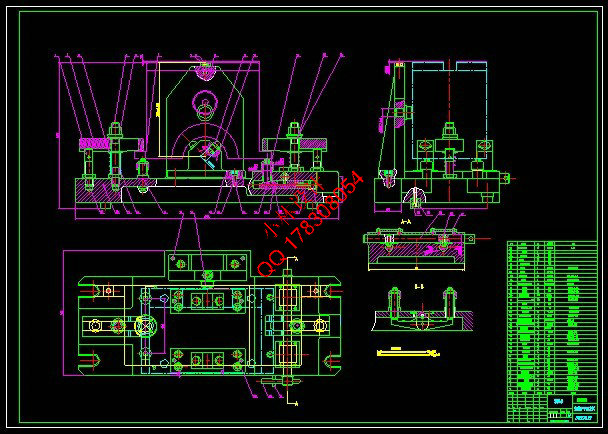
CAD版本图纸,共6张
摘 要
在生产过程中,使生产对象(原材料,毛坯,零件或总成等)的质和量的状态发生直接变化的过程叫工艺过程,如毛坯制造,机械加工,热处理,装配等都称之为工艺过程。在制定工艺过程中,要确定各工序的安装工位和该工序需要的工步,加工该工序的机车及机床的进给量,切削深度,主轴转速和切削速度,该工序的夹具,刀具及量具,还有走刀次数和走刀长度,最后计算该工序的基本时间,辅助时间和工作地服务时间。
箱体零件是一种典型零件,其加工工艺规程和工装设计具有典型性。该箱体零件结构复杂,零件毛坯采用铸造成形。在加工过程中,采用先面后孔的加工路线,以保证工件的定位基准统一、准确。为了消除切削力、夹紧力、切削热和因粗加工所造成的内应力对加工精度的影响,整个工艺过程分为粗、精两个阶段。通过被加工零件的分析完成了机械加工工艺的设计及各加工工序机动时间的计算。根据箱体零件的结构及其功能,运用定位夹紧的知识完成了夹具设计。
关键词:工序;工位;工步;加工余量
Abstract
Enable producing the target in process of production (raw materials, the blank , state of quality and quantity on part become always ) take place direct course of change ask craft course, if the blank is made, machining, heat treatment , assemble etc. and call it the craft course. In the course of making the craft , is it confirm every erector location and worker step that process need this of process to want, the locomotive of processing , this process , and the entering the giving amount of the lathe, cut depth , the rotational speed of the main shaft and speed of cutting, the jig of this process, the cutter and measuring tool, a one hundred sheets of number of times still leaves and a one hundred sheets of length leaves, calculate basic time of this process , auxiliary time and service time of place of working finally.
This box machine element is typical, the manufacturing process and tooling design of it is typical.The structure of this box machine element is complicated, the machine element’s blank adopt casting shape. In the process of manufacture, in order to ensure the location datum accurate and unity, I adopt the manufacturing line from face to hole.In order to clear away the influence for machining accurate of internal stress, cutting force, clamping force, heat in cutting from coarse manufacturing, the whole manufacturing process is made of coarse and accurate manufacturing. Parts were processed through the analysis of the complete machining process design and the manufacturing processes for mobile time calculations. According to the box components and the function and structure, the use of the knowledge positioning clamp completed the fixture design.
Key words:The process;worker one;worker's step;the surplus of processing
目 录
摘 要 III
Abstract IV
目 录 V
1 绪论 1
1.1 本课题的研究内容和意义 1
1.2 国内外的发展概况 1
1.3 本课题应达到的要求 1
2 零件工艺的分析 2
2.1 确定毛坯的制造形式 2
2.2 箱体零件的结构工艺性 2
3 拟定箱体加工的工艺路线 3
3.1 定位基准的选择 3
3.2 加工路线的拟定 3
4 机械加工余量,工序尺寸及毛坯尺寸的确定 6
4.1 机体 6
4.1.1 毛坯的外廓尺寸: 6
4.1.2 主要平面加工的工序尺寸及加工余量: 6
4.1.3 加工的工序尺寸及加工余量: 6
4.2 箱体 6
4.2.1 主要平面加工的工序尺寸及加工余量: 6
4.2.2 加工的工序尺寸及加工余量: 7
5 确定切削用量及基本工时 8
5.1 机座 8
5.1.1 工序5粗铣箱体下平面 8
5.1.2 工序6粗铣箱体分割面 8
5.1.3 工序7磨箱体分割面 9
5.1.4 工序8钻孔 10
5.1.5 工序9钻孔 12
5.1.6 工序10钻孔 14
5.2 机体 16
5.2.1 工序2钻,铰2个直径为6mm深28mm的孔 16
5.2.2 工序4半精铣前后端面 17
5.2.3 工序5半精铣左右端面 18
5.2.4 工序6精前后铣端面 19
5.2.5 工序7精左右铣端面 20
5.2.6 工序9粗镗 21
5.2.7 工序10粗镗 21
5.2.8 工序11半精镗 22
5.2.9 工序12半精镗 23
5.2.10 工序13精镗 24
5.2.11 工序14精镗 24
5.2.12 工序15钻孔在蜗杆轴承孔端面上钻4-M12mm ,深16 mm的螺纹孔 25
5.2.13 工序16钻孔在蜗轮轴承孔端面上钻4-M12mm,深16mm的螺纹孔 26
5.2.14 工序17锪孔 27
6 专用的夹具设计 29
6.1 粗铣下平面夹具 29
6.1.1 问题的指出 29
6.1.2 夹具设计 29
6.2 粗铣前后端面夹具设计 30
6.2.1 定位基准的选择 30
6.2.2 定位元件的设计 31
6.2.3 铣削力与夹紧力计算 32
6.2.4 夹紧装置及夹具体设计 33
6.2.5 夹具设计及操作的简要说明 33
7 结论与展望 34
7.1 结论 34
7.2 不足之处及展望 34
致 谢 35
参考文献 36
|


