小林设计素材网 客服QQ:178308054 Email:178308054@qq.com 机械设计资料 | 相信专业,相信小林 | 小林机械资料网竭诚为您服务!
首页 | 工艺夹具 | 数控编程 | 注塑模具 | 冲压模具 | 机械机电 | 土木工程 | 采矿通风 | 其他专业 | 购买流程 | 信誉说明 | 付款账号 | 加盟
     
您现在的位置: 主页 > 工艺夹具 >
设计名称
空压机曲轴工艺规程设计及系列夹具设计
设计编号
V156
设计软件
AutoCAD, Word
包含内容
见右侧图片
说明字数
19000字
图纸数量
见右侧图片
推荐指数
较高
价格:
价格优惠中
整理日期
2013.09.26
整理人
小林
购买流程
<查看如何购买本站设计>
设计简介

设计描述:

文档包括:
word说明书一份,共45页,约19000字
任务书一份
开题报告一份
外文翻译一份

CAD版本图纸,共6张

毕 业 设 计论 文 任 务 书

一、题目及专题:
1、 题目    空压机曲轴工艺规程设计及系列夹具设计         
2、专题                                                 
二、课题来源及选题依据
       1   无锡力源压缩机有限公司                                              
        2   产品图纸                                                                           

                                                     
      3   产品材料:QT600-3                                         
      4   年产量2000件                                                                      
                                                                
                                                                      
三、本设计(论文或其他)应达到的要求:
 1.工艺规程设计;(工艺过程卡片和工序卡片)                        
 2.夹具设计3套,包括总图及零件图,折合A0图纸不少于3张;                                        

                  
 3.设计说明书一份;(不少于10000字)                                                   
 4.专业论文翻译;(不少10000字符 )                   


摘  要
本次设计的主要内容包括空压机曲轴的工艺规程设计和系列夹具设计的两大方面。
制定工艺规程设计的原始资料包括:零件的图样,产品验收质量标准,产品的年生产纲领和生产类型、毛坯

图样、生产条件、零件材料等。制定工艺规程设计步骤如下:审查零件的图样,工艺方案的确定,对样品进

行工艺分析,零件的毛坯选择以及毛坯图说明; 工艺设计过程(包括加工段的分析,工序的集中和分散,工

序顺序的安排,定位基准的选择,零件表面加工方法的选择); 制定工艺路线(工艺方案,工艺方案的比较与

分析),工序间尺、公差、表面粗糙度及毛坯尺寸的确定,加工余量、切削用量、工时定额的确定,填写工

艺文件。夹具设计必须满足的要求有:保证加工精度,夹具的总体方案应与年生产纲领相适应,安全、方便

、减轻劳动强度,排屑顺畅,具有良好的强度、刚度和结构工艺性。夹具设计包括工件的定位,定位误差的

分析与计算,夹紧机构的确定,夹具力的确定(包括方向,作用点和大小)。
    当工艺规程及夹具设计确定后,再绘制夹具总装配图、主要零件图和说明书的编写。

关键词:工艺规程设计;夹具设计;加工余量;定位误差

Abstract
    The design of the main contents include two aspects of the M3400 thermostat process

planning and fixture series.
    The original development of process planning include: part drawings and assembly drawings

must be quality standards for product acceptance, the agenda for the annual production and

production type, rough drawings, production conditions. Development of process planning, follow

these steps: review of part design, process analysis part, select the part of the rough, draw a

rough diagram, process design (including positioning reference choice, the choice of the parts

of the surface processing methods, processing the order of arrangement process combinations),

process design (including choice of machine tool equipment and tooling, the determination of

allowance in the process, the process of determination of dimensions and tolerances, the choice

of cutting the amount of time quota determined), the technical and economic analysis, the

complete process documents. The fixture design requirements that must be met: ensure accuracy

the fixture overall program should be adapted to the agenda for the annual production, safe,

convenient, reduce labor intensity and smooth chip, has good strength, stiffness and structure

of the process. Fixture design including jigs and fixtures design overview, the choice of

positioning with locating datum clamp mechanism design, positioning error analysis and

calculation, the clamping mechanism to determine the clamping force OK.
    When the process planning and fixture design is determined, and then draw a the fixture

assembly drawings, preparation of the main parts diagram and instructions.

Keywords: process planning; fixture design; allowance; positioning error
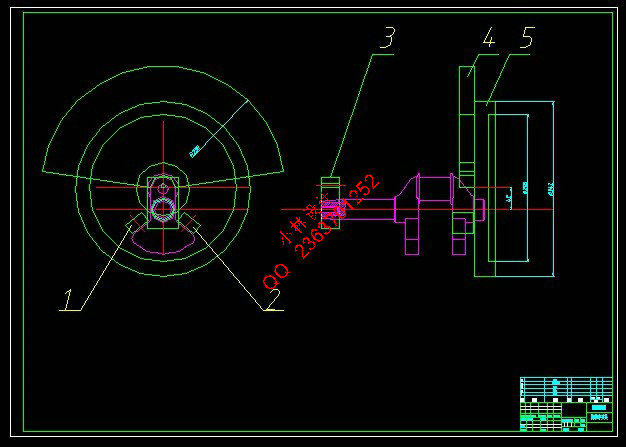
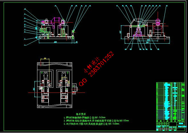
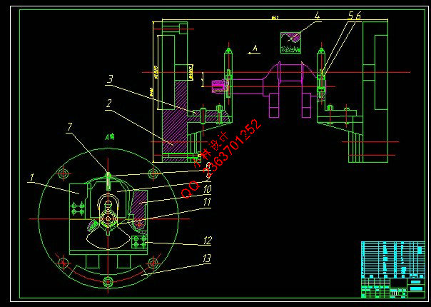
 
目  录
摘  要 III
Abstract IV
目  录 V
1 绪论 1
1.1 本课题研究的内容及意义 1
1.2 国内外发展情况 1
1.3 本课题应达到的要求 2
2 工艺方案的确定 3
2.1 曲轴零件的结构特点 3
2.2 曲轴零件的技术要求 3
3 零件工艺分析 4
3.1 根据零件图和产品装配图,对零件进行工艺分析 4
3.2 计算零件的生产纲领,确定生产类型 4
4 毛坯选择和毛坯图说明 5
4.1 毛坯技术分析 5
4.2 确定毛坯种类和制造方法 5
4.3 确定毛坯总余量 5
5 工艺设计过程 6
5.1 加工阶段的划分 6
5.2 工序的集中与分散 6
5.3 工序顺序的安排 6
5.4 定位基准的选择 6
5.5 零件的表面加工方法的选择 6
6 制定工艺路线 7
6.1 工艺路线方案一 7
6.2 工艺路线方案二 7
6.3 工艺方案的比较与分析 8
7 工序间尺寸、公差、表面粗糙度及毛坯尺寸的确定 9
8 加工余量,切削用量,工时定额的确定 10
8.1 工序一:铣两端面,打中心孔 10
8.1.1 工步一:铣两端面 10
8.1.2 工步二:两端面打中心孔 10
8.2 工序二:粗车大端主轴颈及平衡块外轮廓 11
8.2.1 工步一:粗车大端Φ40主轴颈外圆面及轴肩 11
8.2.2 工步二:车平衡块Φ174外轮廓 11
8.3 工序三:粗车小端外轮廓 12
8.3.1 工步一:粗车小端Φ40主轴颈外圆面及轴肩 12
8.4 工序四:半精车大端主轴颈及倒角 12
8.4.1 工步一:半精车大端Φ40主轴颈外圆面及轴肩 12
8.5 工序五:精车大端主轴颈及倒角 13
8.5.1 工步一:精车大端Φ40主轴颈外圆面及轴肩 13
8.5.2 工步二:精车大端主轴颈上1×45°倒角 14
8.6 工序六:半精车Φ40外圆面及轴肩锥面、小端锥面 14
8.6.1 工步一:半精车小端Φ40主轴颈外圆面及轴肩 14
8.6.2 工步二:倒Φ40主轴颈上角 15
8.7 工序七:铣键槽 15
8.7.1 工步一:铣键槽 15
8.8 工序八:精车Φ40外圆面及轴肩锥、小端锥面 16
8.9 工序九:粗车连杆轴颈及其轴肩 17
8.9.1 工步一:粗车连杆轴颈及其轴肩 17
8.10 工序十:半精车连杆轴颈及其轴肩 17
8.10.1 工步一:半精车连杆轴颈及其轴肩 17
8.11 工序十一:精车连杆轴颈及其轴肩 18
8.11.1工步一:精车连杆轴颈及其轴肩 18
8.12 工序十二:打通孔及打M12螺纹孔并攻丝 18
8.12.1 工步一: 打通孔 18
8.13 工序十三:主轴颈、连杆轴颈淬火 19
8.14工序十四:磨连杆轴颈外圆及其轴肩面 19
8.15工序十五:磨大端主轴颈及其轴肩面 20
8.15.1工步一:磨大端主轴颈及其轴肩面 20
8.16工序十六:磨小端主轴颈及其轴肩面 20
8.16.1工步一:磨小端主轴颈及其轴肩面 20
8.17工序十七:去毛刺 21
8.18工序十八:检验 21
9 专用夹具设计 22
9.1 机床夹具设计概述 22
9.1.1 机床夹具概述 22
9.1.2 机床夹具的分类 22
9.1.3 机床夹具的组成和功用 22
9.1.4 夹具总体方案设计 23
9.2 夹具设计 24
9.2.1 问题的提出 24
9.2.2 定位方式与定位基准的选择 24
9.2.3 夹具机构设计 24
9.2.4 定位销长度的分析 26
9.2.5 定位误差的分析与计算 26
10 结论与展望 32
10.1 结论 32
10.2 不足之处与未来展望 32
致  谢 33
参考文献 34

部分图纸
截图


说明:
如需了解本设计的具体详细信息请联系本站客服,说明看哪个设计(编号)哪个详细部分,我们将远程或截图给您观看.
机械毕业设计|论文
[要求PR≥2,百度收录≥1000页;联系QQ:178308054]
  • pass',
  • 最新选题目录 - 购买流程 - 信誉说明! - 付款账号 - 帮助中心
    声明:根据《互联网传播权保护条例》本站,小林机械资料商城,所列资料均属原创者所有,仅供学习交流之用,请勿转载并做其他非法用途。
    Powered by 小林机械资料商城 © 2013-2020 All Rights Reserved. 客服QQ:178308054
    喜欢www.xiaolinbysj.com,请告诉你QQ上的5位好友,多谢您的支持! 皖ICP备2021006205号-1 辰光云统计平台