设计描述:
文档包括:
说明书一份,29页,约18000字
工序卡一套
过程卡片一套
CAD版本图纸,共5张
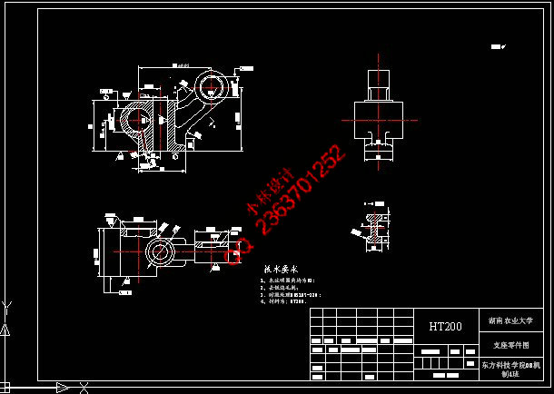
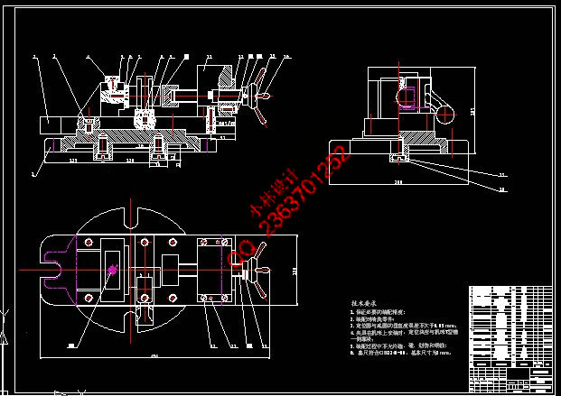
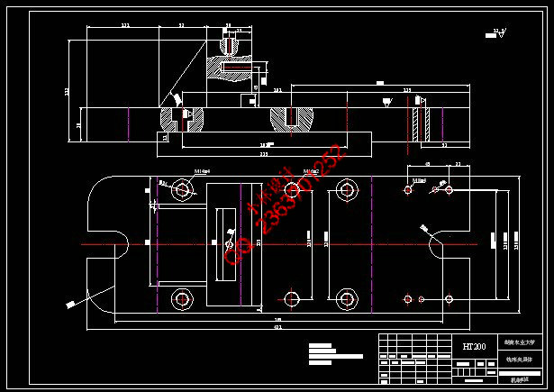
支座加工工艺及其夹具设计
摘 要:本设计是支座加工工艺及其夹具设计,主要任务是半精铣36mm下端面和钻Φ18孔、支座的加工工
艺规程编制、编写工序卡片。其零件为铸件,具有体积小,零件结构简单的特点,此零件的孔加工精度高
于面,所以采用先面后孔的加工顺序,各工序夹具都采用专用夹具,其中在钻Φ18孔时,采用了液压夹紧
,机构设计简单,方便且能满足要求。
关键词:加工工艺;工艺规程编制;夹具设计
The Design of Bearing Processing Technology and Fixture
Abstract:This paper is designed for bearing processing technology and fixture. The main task
is to work out the half fine milling under 36mm,Φ18 holes, bearing the processing technology
of the rules of procedure, and write CARDS. Its parts are casting, which is small and of
simple structure. Moreover, the components of the hole processing is higher than that of the
surface, so the processing order of surface first is taken. The fixture special jig is
adopted in each working procedure.,among which in a drill Φ18 holes, the hydraulic clamping
is used, which is simple, convenient and can meet the requirements.
Keywords:Processing technology;Design of process flow;Design of clamp
目 录
摘要…………………………………………………………………………………………1
关键词………………………………………………………………………………………1
1 前言………………………………………………………………………………………1
1.1 选题研究意义和国内外研究现状………………………………………………1
1.2 课题背景知识 ……………………………………………………………2
1.2.1 零件作用…………………………………………………………………2
1.2.2 柴油机相关知识介绍……………………………………………………3
2 支座的机械加工工艺规程设计…………………………………………………………3
2.1 零件的工艺分析及生产类型的确定……………………………………………3
2.1.1 零件的作用………………………………………………………………3
2.1.2 零件的工艺分析…………………………………………………………4
2.1.3 确定零件的生产类型……………………………………………………5
2.2 选择毛坯种类,绘制毛坯图……………………………………………………6
2.2.1 选择毛坯种类……………………………………………………………6
2.2.2 确定毛坯尺寸及机械加工总余量………………………………………7
2.2.3 设计毛坯图…………………………………………………………8
2.2.4 绘制毛坯图…………………………………………………………8
2.3 选择加工方法,制定工艺路线……………………………………………9
2.3.1 粗基准的选择………………………………………………………9
2.3.2 精基准选择的原则…………………………………………………9
2.4 各表面的加工方法的选择……………………………………………………10
2.5 加工阶段的划分和工序集中与分散的确定…………………………………11
2.6 工序的安排……………………………………………………………………12
2.7 工序的机床设备、工艺装备和辅助工具………………………………………13
2.8 机械加工余量、工序尺寸及公差的确定……………………………………14
2.9 切削用量和时间定额的确定…………………………………………………15
3 支座专用夹具的设计…………………………………………………………………22
3.1 半精铣36mm下端面夹具设计…………………………………………………22
3.1.1 确定定位方案,选择定位元件…………………………………………22
3.1.2 切削力及夹紧分析计算………………………………………………23
3.1.3 确定夹紧机构…………………………………………………………24
3.1.4 确定夹具体装置………………………………………………………24
3.1.5 绘制夹具总图…………………………………………………………24
3.2 孔加工夹具设计………………………………………………………………25
3.2.1 确定定位方案,定位基准的选择……………………………………25
3.2.2 定位误差分析…………………………………………………………25
3.2.3 导向装置的确定………………………………………………………25
3.2.4 夹紧装置的设计………………………………………………………25
3.2.5 切削力及夹紧力的计算………………………………………………26
3.2.6 检验夹紧元件的强度…………………………………………………27
3.2.7 设计夹具体……………………………………………………………27
3.2.8 液压控制回路的确定…………………………………………………28
3.2.9 液压回路的综合和整理………………………………………………29
4 结论……………………………………………………………………………29
5 参考文献 ………………………………………………………………………………31
致谢…………………………………………………………………………………………31
附录…………………………………………………………………………………………32
|