设计简介 |
文档包括:
说明书一份,63页,月20000字
工序卡片一套
加工过程卡一套
CAD版本图纸共4张
摘 要
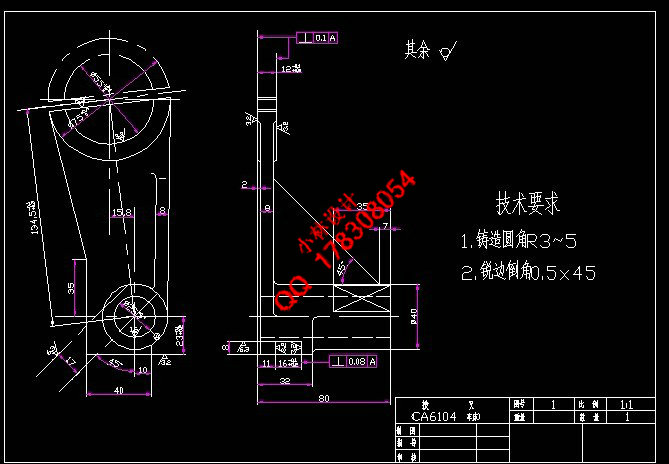
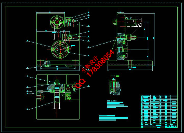
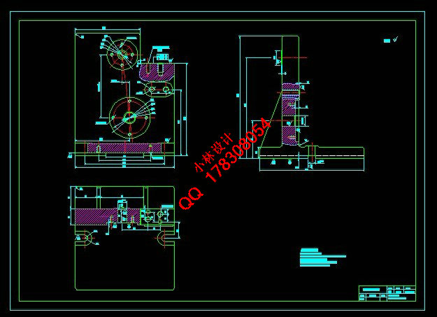
本设计是车床拨叉零件的加工工艺及专用夹具设计。从零件的结构外型分析,它的外型复杂,且不易加工,因此该零件选用是铸造件。它的主要加工面是孔、拨叉叉口两端面和槽,在加工中由于面的加工精度要比孔的加工精度容易保证。因此,在设计中采用先面后孔的原则,并将孔与平面的加工划分为粗加工和精加工阶段,以保证加工精度。在本设计中,先以一个面加工出一个基准面,然后,再以该基准面加工相应的孔。在后面的工序中,均以该孔为定位基准,加工拨叉叉口两端面、孔、底平面、槽和斜平面,在整个加工过程中,分别采用了铣床、钻床和镗床。并设计了铣侧面、镗孔和铣槽等的专用夹具,并对它们的定位都采用了一面两销定位。由于该零件的尺寸不大,所需的夹紧力不大。因此,夹紧方式都采用手动夹紧,它的夹紧简单,机构的设计更为方便,满足夹紧要求。
关键词 拨叉零件,加工工艺,专用夹具,定位, 夹紧
ABSTRACT
This design is a lather plectrum parts processing and special fixture designs. Parts from the appearance of the structure, its appearance complex and difficult process, so the selection of parts is casting.The parts are cast parts. In the processing, it is easier to ensure the processing accuracy of plane than the hole. So the parts’ main planes are hole, two blades of the Plectrum and groove. Therefore, in the design, it adopts the principle of plane first and hole second and divides the hole and plane’s working into extensive and intensive processing stages so as to ensure the accuracy. In this design, firstly, it uses the plane to work a datum; secondly, it uses the datum to work according hole. And in the latter process of working, it also takes hole as the poisoning base and works the two bales of Plectrum, hole, bottom plane, groove and inclined plane. In the entire machining process, it uses separately the milling machine, driller and boring machine. And the design aspect of milling, boring and milling ducts special fixture. They also have adopted the positioning of a two marketing positioning. According to the requirement, it designs the special fixture. For the size of parts is not very big, it doesn’t require strong clamping force. Therefore, methods of clamping are manual clamping; that is because it is simple and the design is more convenient to meet the requirements of clamping.
Keywords Plectrum Parts, Processing, Special Fixture, Positioning, Clamping
目 录
摘 要………………………………………………………………………………………Ⅰ
ABSTRACT…………………………………………………………………………………… Ⅱ
1 绪论……………………………………………………………………………………………1
2 拨叉A的分析…………………………………………………………………………………2
2.1零件的作用…………………………………………………………………………………… 2
2.2拨叉A的工艺分析……………………………………………………………………………2
2.3拨叉A的工艺要求……………………………………………………………………………2
2.3.1加工要求……………………………………………………………………………2
2.3.2平面的加工………………………………………………………………………………3
2.3.3大头孔的加工…………………………………………………………………………3
2.3.4 小头孔的加工……………………………………………………………………………3
2.4本章小结……………………………………………………………………………………3
3 工艺规程设计…………………………………………………………………………………5
3.1确定毛坯的尺寸形式…………………………………………………………………………5
3.2加工工艺过程…………………………………………………………………………………5
3.3定位基准的选…………………………………………………………………………………5
3.3.1粗基准的选择……………………………………………………………………………5
3.3.2 精基准的选择………………………………………………………………………6
3.4工艺路线的拟订………………………………………………………………………………6
3.4.1确定工序的原则…………………………………………………………………………6
3.4.2工序的特点………………………………………………………………………7
3.4.3加工精度的划分…………………………………………………………………………8
3.4.4制定工艺路线…………………………………………………………………………8
3.5本章小结…………………………………………………………………………………10
4 工序参数选择、计算………………………………………………………………………11
4.1毛坯的确定……………………………………………………………………………11
4.1.1毛坯的工艺要求………………………………………………………………………11
4.1.2 毛坯形状、尺寸要求……………………………………………………………………11
4.2 拨叉A偏差的计算…………………………………………………………………………12
4.2.1 拨叉平面的偏差及加工余量计算……………………………………………………12
4.2.2 大小头孔的偏差及加工余量计算……………………………………………………13
4.2.3铣 槽的偏差及加工余量计算…………………………………………………14
4.3确定切削用量及基本工时…………………………………………………………………14
4.3.1粗、精加工小头孔端面…………………………………………………………………14
4.3.2加工孔 到要求尺寸………………………………………………………………16
4.3.3粗、精铣叉口两侧面……………………………………………………………………20
4.3.4粗、精镗 孔…………………………………………………………………………22
4.3.5粗、精铣下平面…………………………………………………………………………23
4.3.6 粗、 精铣 槽……………………………………………………………………25
4.3.7粗铣斜平面…………………………………………………………………………26
4.3.8铣断……………………………………………………………………………………26
4.4时间定额计算及生产要求…………………………………………………………………26
4.4.1粗、精加工小头孔端面…………………………………………………………………27
4.4.2加工孔 到要求尺寸………………………………………………………………27
4.4.3粗、精铣叉口两侧面……………………………………………………………………27
4.4.4粗、精镗 孔…………………………………………………………………………28
4.4.5粗、精铣下平面…………………………………………………………………………28
4.4.6粗、精铣 槽………………………………………………………………………29
4.4.7粗铣斜平面…………………………………………………………………………30
4.4.8铣断……………………………………………………………………………………30
4.5本章小结……………………………………………………………………………30
5 镗孔夹具设计………………………………………………………………………………31
5.1镗孔夹具设计………………………………………………………………………………31
5.1问题的提出……………………………………………………………………………31
5.2定位基准的选择…………………………………………………………………………31
5.3夹具方案的确定…………………………………………………………………………32
5.4误差分析与计算…………………………………………………………………………33
5.5 切削力及夹紧力的计算……………………………………………………………………35
5.6 镗床夹具分析………………………………………………………………………………37
5.7 本章小结……………………………………………………………………………………38
6铣侧面夹具设计……………………………………………………………………39
6.1定位基准的选择…………………………………………………………………………39
6.2 夹具方案的确定……………………………………………………………………………40
6.3 定位误差的分析及计算……………………………………………………………………40
6.4切削力及夹紧力的计算…………………………………………………………………41
6.5定向键与对刀装置的选择………………………………………………………………42
6.6 本章小结……………………………………………………………………………………44
7铣槽夹具设计……………………………………………………………………………45
7.1定位基准的选择…………………………………………………………………………45
7.2制定夹具设计方案………………………………………………………………………45
7.3定位元件的选择…………………………………………………………………………47
7.4定位误差分析…………………………………………………………………………48
7.5铣削力与夹紧力计算……………………………………………………………………49
7.6定向键与对刀装置的选择………………………………………………………………50
7.7本章小结…………………………………………………………………………………52
8 结论 …………………………………………………………………………………………53
参考文献………………………………………………………………………………………54
致谢……………………………………………………………………………………………55
|