|
文档包括:
说明书一份,29页,约21000字
任务书一份
开题报告一份
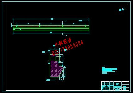
CAD版本图纸共6张
主要内容和要求(宋体五号,行间距单倍行距)
设计的主要内容:
一、建立数学模型。
二、进行方案选择,要求论证充分。
三、整体结构设计,绘制0号结构示意图一张。
四、编写运算程序。
五、测绘零件图1号图一张。
六、编写设计计算说明书一份,不少于15000字。
主要参考资料(具体格式以规范化要求规定为准)
[1] 常健生.检测与转换技术.[M] 机械工业出版社 2002年2月
[2] 樊映川. 数学分析.[M]人民教育出版社 1980年6月
[3] 朱龙根. 机械零件设计手册 [M] 机械工业出版社2001年8月
[4] 王光斗,王春福.机床夹具设计手册 [M]上海科学技术出版社1988年3月
[5] 方大千. 电工手册 [M] 电子出版社2003年10月
[6] 温松明. 互换性与技术测量基础 [M]长沙:湖南大学出版社2000年10月
[7] 谭浩强. C程序设计 [M]北京:清华大学出版社1997年1月
[8] 陆耀祖. 内燃机构造与原理 [M]中国建材工业出版社2004年3月
[9] 卡严.机械传动装置设计手册 [M]北京:机械工业出版社1997年1月
[10] 王世彤. 机械原理与零件 [M] 北京:高等教育出版社2004年3月
[11] 符炜. 机械创新设计构思方法 [M] 湖南科学技术出版社2005年1月
[12] 孙恒 陈作模. 机械原理[M] 北京:高等教育出版社1996年5月
目 录
摘要……………………………………………………………………………1
关键词…………………………………………………………………………1
1前言………………………………………………………………………………2
1.1选题研究意义 …………………………………………………………………2
1.2国内外研究现状………………………………………………………………2
1.3课程研究内容 …………………………………………………………………3
2 形位误差检测原理…………………………………………………………………3
2.1形位误差检测的特点……………………………………………………………3
2.2形位误差检测的基本原则………………………………………………………4
2.3同轴度测量的数学模型…………………………………………………………5
2.4最小二乘法测量……………………………………………………………7
2.4.1测量原理……………………………………………………………7
2.4.2计算机处理程序……………………………………………………………8
3方案论证……………………………………………………………………10
3.1方案一 …………………………………………………………………10
3.2方案二………………………………………………………………11
3.3方案三 ………………………………………………………………………11
3.4小结 ………………………………………………………………………11
4检测系统设计……………………………………………………………………… 11
4.1测量部分……………………………………………………………11
4.2计算机控制处理及测量过程…………………………………………………12
4.3机械部分……………………………………………………………13
4.3.1驱动电机的选择…………………………………………………………13
4.3.2工件的定位……………………………………………………………19
4.3.3机身设计……………………………………………………………19
4.3.4导轨截面设计……………………………………………………………21
4.3.5滚珠丝杠螺母副设计……………………………………………………23
4.3.6滚动轴承的选择…………………………………………………………26
4.3.7传感器支架弯度校核……………………………………………………28
5结论…………………………………………………………………28
参考文献 ………………………………………………………………………29
致谢……………………………………………………………………………30
摘 要:本文介绍了曲轴轴线同轴度误差自动检测仪设计的详细过程,其中运用最小二乘法原理建立了曲轴轴线同轴度误差检测原理的数学模型,对检测装置的组成部分进行了详细的分析及运算,提出了多套设计方案,并选择其中一种进行了详细地说明和计算,包括对床身的结构设计、驱动用电动机的选择、测量装置的选择、对主要的传动部件进行计算和校核,并列出了多个图表进行补充说明,还绘制了检测系统原理图、组成联系图、检测装置的装配图和部分零件图。根据原理编写了对已采集数据进行计算处理的程序。
关键词:同轴度误差;数学模型;自动检测及数据分析
THE DESIGN OF AUTOMATIC DETECTOR FOR COAXIALITY OF CRANKSHAFT
Abstract: This paper introduced the axis of the crankshaft coaxiality automatically detect errors in detail the process of home design, according to the principle of least squares to establish the axis of the crankshaft coaxiality error detection principle of mathematical model of detection devices have been an integral part of detail and put forward a number of sets of design options, and select one of a detailed explanation and calculation, including the bed of the structural design, the choice of driving motor, the choice of measuring devices, the main components of the calculation of transmission and checking, and set out a number added to the chart. Drawing a schematic diagram detection system, composed of linked maps, detection devices and parts assembly diagram. Prepared in accordance with the principle of the calculation has to deal with data collection procedures.
Key words: coaxiality error; mathematical model; automatic detection and the data analysis;
| 


