 |
 |
|


|
设计名称 |
缸体气缸孔镗削动力头的设计 |
 |
|
设计编号 |
B052 | |
|
设计软件 |
AutoCAD, Word | |
|
包含内容 |
见右侧图片 | |
|
说明字数 |
14000字 | |
|
图纸数量 |
见右侧图片 | |
|
推荐指数 |
较高 | |
|
价格: |
价格优惠中 | |
|
整理日期 |
2013.09.26 | |
|
整理人 |
小林 | |
|
购买流程 |
<查看如何购买本站设计> |
|
设计简介 |
设计描述:
文档包括: CAD版本图纸共14张
主要内容和要求(宋体五号,行间距单倍行距)
The Design of Boring Machine Kinetic Head For Cylinder Hole
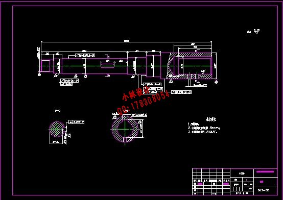
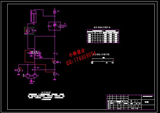
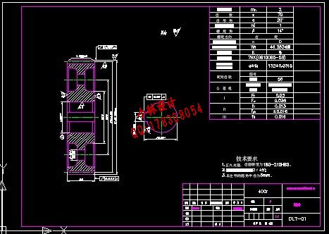
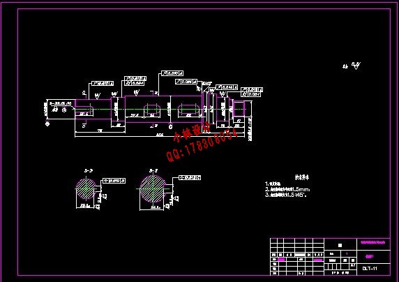
Abstract: In the machine tool, the boring head is the core component of the machine, which reflects the processing performance directly. And the design of boring head itself and whether the precision of manufacture achieves certain degree decide whether the parts can achieve processing requirements. This design is about boring head, which is used for machining cylinder hole. I firstly focused on how to determine the kinematics parameters and kinematical programs of the boring head. Then, on the basis of the power transmission project, I designed the spindle box, namely the spindle box, spindle, transmission shaft and the parameter selection, selected spindle and drive shaft bearings and do the checking. I used hydraulic transmission in feeding movement of power head,and designed and calculated the hydraulic system to get a full hydraulic transmission system. In this way, I finally accomplished the design of a boring head.
目 录
摘要 1 |
|
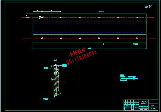
部分图纸 截图 |
        |
|
说明: |
如需了解本设计的具体详细信息请联系本站客服,说明看哪个设计(编号)哪个详细部分,我们将远程或截图给您观看. 机械毕业设计|论文 |

| [要求PR≥2,百度收录≥1000页;联系QQ:178308054] |
Powered by 小林机械资料商城 © 2013-2020 All Rights Reserved. 客服QQ:178308054
喜欢www.xiaolinbysj.com,请告诉你QQ上的5位好友,多谢您的支持! 皖ICP备2021006205号-1
