 |
 |
|


|
设计名称 |
基于PLC的备用电源自动投入装置的设计 |
 |
|
设计编号 |
B065 | |
|
设计软件 |
AutoCAD, Word | |
|
包含内容 |
见右侧图片 | |
|
说明字数 |
17000字 | |
|
图纸数量 |
见右侧图片 | |
|
推荐指数 |
较高 | |
|
价格: |
价格优惠中 | |
|
整理日期 |
2013.09.26 | |
|
整理人 |
小林 | |
|
购买流程 |
<查看如何购买本站设计> |
|
设计简介 |
设计描述:
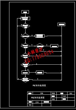
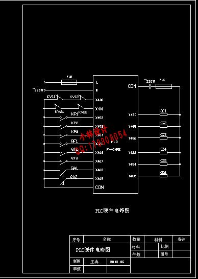
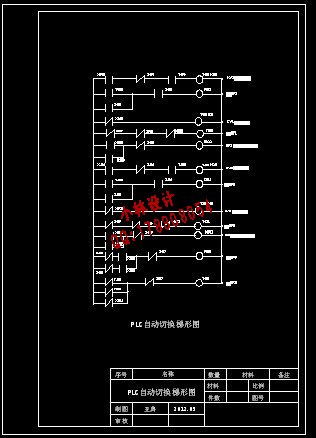
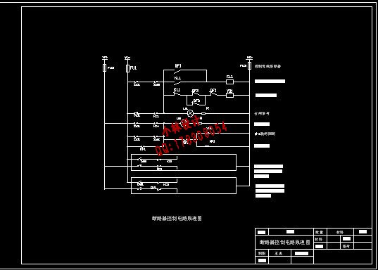
文档包括: CAD版本图纸,共5张 基于PLC的备用电源自动投入装置的设计
摘要:本文介绍了三菱可编程逻辑控制器PLC(Programmable Logic Controller)在备用电源中的应用。PLC采集一次设备的正常运行状态信号,作为备用电源自动投入的启动条件和闭锁条件,通过编程来实现不同的功能,以适应不同的运行方式。与继电器组成的备用电源自动投入装置相比,该方案具有可靠性高、接线简单、控制灵活、调试方便和投资小等优点。因此,可编程逻辑控制器在电力系统自动化领域中得以广泛应用。
Design of Alternate Power Auto-Cast Device Based on PLC
Abstract: A scheme of programmable logic controller PLC(Mitsubishi FX ) which putts into the backup power automatically was introduces in this paper . PLC gathers the first equipment the normal operation of state signal as launce conditions and closed conditions of putting into the backup power automatically and through programming to achieve different functions to adapt to different operating manner. Compared with the relay consistence of putting into the backup power automatically device, this scheme has advantages of high reliability, simple wiring, control flexibility, convenience debugging, small investment and so on. Therefore, the programmable logic controller is widely used in the field of power system automation.
摘要…………………………………………………………………………………………1 |
|
部分图纸 截图 |
     |
|
说明: |
如需了解本设计的具体详细信息请联系本站客服,说明看哪个设计(编号)哪个详细部分,我们将远程或截图给您观看. 机械毕业设计|论文 |

| [要求PR≥2,百度收录≥1000页;联系QQ:178308054] |
Powered by 小林机械资料商城 © 2013-2020 All Rights Reserved. 客服QQ:178308054
喜欢www.xiaolinbysj.com,请告诉你QQ上的5位好友,多谢您的支持! 皖ICP备2021006205号-1
