|
设计描述:
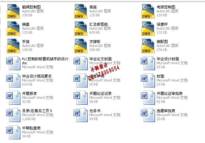
文档包括:
说明书一份,40页,月18000字
CAD版本图纸,共8张
主要内容和要求(宋体五号,行间距单倍行距)
1、 技术规范
移置零件形状:轴类零件: 100*300
主要设计参数:零件重量:5kg;
2、 设计任务
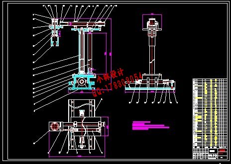
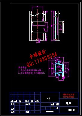
1 ) 绘制系统装配图,0号图纸一张。
2)绘制PLC原理图,编写PLC程序,1号图纸一张。
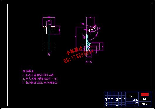
3)测绘零件图,1号图纸2张。
4)编制设计计算说明书,不少于15000字。
3、设计要求
1)按技术规范要求的参数进行强度设计。
2)图纸绘制符合国家标准要求。
3)设计计算说明书格式符合学校的规定,内容完整、计算正确、分析深入。
PLC控制的移置机械手的设计
摘 要:机械手是在机械化、自动化过程中发展起来的一种新型装置。它能模仿人手部分动作,按照预先设定的程序,轨迹或其他要求,实现抓取,搬运工件或操纵工具的机械化装置。在现代生产中,机械手被广泛应用于自动生产线,机器人的研究和生产已经成为高科技领域内,迅速发展起来的一门新兴的技术,它促进了机械手的发展,使得机械手能更好的与机械化、自动化有机结合。
本文的移置机械手的设计,采取直角坐标式运动形式的机械手,液压驱动的方式,通过液压缸,阀,油泵,油箱等实现运动。同时采用PLC控制电磁换向阀,控制油缸的进油,从而控制机械手的直线移置运动,进而实现其自动化,具有提高生产效率,实现实时控制的意义。
关键词:机械手;PLC;液压缸;电磁换向阀
The Design of Robot displacement Manipulator Based on PLC Control
Abstract: Manipulator is one kind of new model device automating to develop in process in mechanization.It can imitate humen’s hand action. According to the predetermined programme, track and other requirements. Realize grabing carrying workpieces and operating tools by a Mechanization device. In the production of now, manipulators are widely used in automatic production line. Robot in the research and production has become a new developing rapidly technology in a high-tech area. It has promoted the development of manipulator .Especially,making manipulator can better implementation and mechanization, automation organic integration.
The writing of moving manipulator design,Adopt dyadic motion of right angle coordinate form manipulator, way that hydraulic pressure drives, by the hydraulic cylinder , valve , oil pump,the fuel tank and so on to realizing motion. at the same time ,Adopt PLC to control electromagnetism changing-over valve. controlling oil moving forward to oil jar, So as to control of the manipulator linear movement of sports, and achieve its automation, With increasing production efficiency, realizing the significance of the real-time control.
Key words: Manipulator;PLC;Hydraulic cylinder;Electromagnetism changing-over valve
目 录
摘 要 1
关键词 1
1 前言 2
1.1 选题研究意义 2
1.2 PLC起源 2
1.3 PLC的发展 3
1.4 PLC工作原理 3
1.5 PLC功能特点 4
2 PLC的结构及基本配置 5
2.1 PLC的CPU的地位 5
2.2 PLC的CPU功能 5
2.3 PLC的存储器 6
2.4 PLC 的外部设备 7
2.5 PLC的选型 7
2.6 PLC的工作过程 8
3 机械手发展概况 10
3.1 机械手国内发展现状 11
3.2 机械手的国外发展现状 11
3.3 各类机械手的比较 12
4 总体方案的设计与分析 14
4.1 机械手设计的总体方案 14
4.2 手指的夹紧力的计算 15
4.3 手臂结构设计 15
5 液压缸主要参数的确定 15
5.1 夹紧缸夹紧力的计算 15
5.2 X方向移动的受力计算 16
5.3 Z向移动的受力计算 16
5.4 Y方向移动的受力计算 17
6 液压系统主要参数计算 17
6.1 选择系统的工作压力 17
6.2 确定执行元件的几何参数 17
6.2.1 确定夹紧缸机构尺寸 18
6.2.2 X方向移动缸结构尺寸 18
6.2.3 Y方向横移缸机构尺寸计算 18
6.2.4 Z方向升降缸机构尺寸计算 18
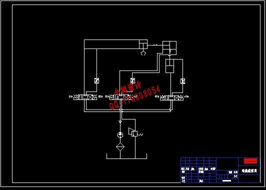
7 拟定液压系统原理图 19
7.1 系统运动回路的设计 19
7.1.1 X方向运动回路的设计 19
7.1.2 Y方向运动回路的设计 19
7.1.3 Z方向升降运动回路的设计 20
7.1.4 夹紧缸动作回路的设计 20
7.2 拟定液压系统原理图 20
8 液压元件的选择 21
8.1 选择液压泵 21
8.1.1 确定液压泵的最大工作压力 21
8.1.2 确定液压泵的流量 22
8.2 确定液压泵驱动电机功率 22
8.3 选择辅助元件 22
8.4 确定油箱的容量 23
8.5 液压阀的选择 23
9 液压系统的性能验算 24
9.1 回油路压力损失的验算: 24
9.2 局部压力损失验算: 24
9.3 计算液压系统的发热温升 25
9.4 重要连接部位螺钉强度的校核 26
10 PLC控制系统的设计 27
10.1 设计该机械手控制程序的步骤和方法 27
10.2 PLC机械手控制程序设计 28
10.2.1 机械手控制的公用程序 30
10.2.2 手动程序 31
10.2.3 自动程序 32
10.2.4 自动回原点程序 33
11 结论 34
参考文献 34
致谢 35
附录 35
| 


