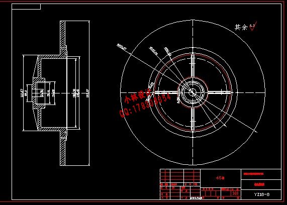
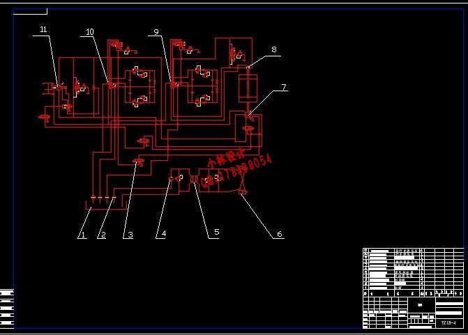
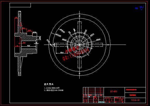
设计描述:
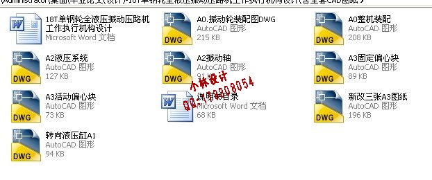
文档包括:
说明书一份,31页,月16000字
CAD版本图纸,共10张
18T单钢轮全液压振动压路机工作执行机构设计
摘 要:伴随着我国基础设施建设的大力开展,市场对工程机械的需求量显著增加。机场、港口、道路等建设项目对工程机械提出了更高的要求。振动压路机是工程施工中的重要设备之一,其工作性能将直接影响到工程的质量。
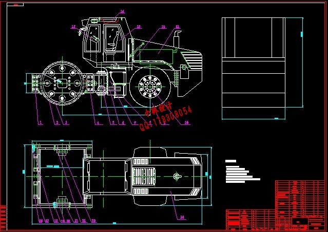
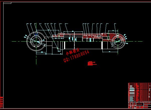
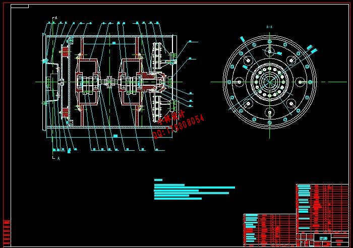
论文介绍了振动压路机在国内外的发展历程和发展趋势,介绍了振动压路机的基本组成机构,并对18T单钢轮全液压振动压路机进行了整体的初步设计,确定了其基本参数。文中重点对18T单钢轮全液压振动压路机的工作执行机构——-振动轮做了较为详细的设计计算,计算了激振力的大小,并对振动轴的强度进行了校核。此外,论文还对转向液压油缸进行了设计。
关键词:振动压路机;振动轮;转向液压缸;激振力;
18TSlnglie Steelwheel of Hydrau Licvib Ratory Rollera Ctuating Mechanism Desing
Abstract:Along with the strenuous development of the infrastructure in China, the demand of engineering machinery in market remarkablely increased. The constructure projects such as airports, ports, roads have raised higher request for engineering machinery.The vibratory roller is one of the important facilities in engineering construction. Its performance will directly affect the quality of the project.
The article introduces the development course and tendencies of vibratory rollers both at home and abroad. It also gives an introduction about the basic composition of the vibratory roller. What’s more, it makes an overall preliminary design for the YZ18 hydraulic vibratory roller and determines the basic parameters of it. The key point of this article lies in detailed design and calculation of vibratory wheel, which is the working actuator of YZ18 hydraulic vibratory roller. It calculates the size of the exciting force and verifies the intensity of the vibrating shaft. In addition, this paper also makes a design for the steering hydraulic cylinder.
Keywords: vibratory roller;vibratory wheel;steering hydraulic cylinder;exciting force
目 录
摘要 1
关键词 1
1 前言 2
1.1 振动压路机的发展概况 2
1.1.1 压路机的分类 2
1.1.2 压路机的发展历史 2
1.1.3 振动压路机的国外发展状况 3
1.1.4 振动压路机的国内发展状况 4
1.1.5 振动压路机的发展趋势 5
1.2 压路机的振动压实原理 5
1.3 本设计的主要任务 6
2 振动轮的设计计算 6
2.1 偏心块的设计计算 7
2.2 挡销的选择与校核 10
2.3 振动轴承的选择 11
2.3.1 振动轴承受力分析 11
2.3.2 振动轴承选型 13
2.3.3 轴承精度 14
2.4 框架轴承 14
2.5 振动轴的设计计算 15
2.5.1 振动轴的形状 15
2.5.2 振动轴的最小直径计算 15
2.5.3 连轴器选择 16
2.5.4 振动器壳体设计 16
2.5.5 振动轴强度校核 17
2.5.6 振动轴承寿命校核 19
2.6 振动功率的计算 19
2.6.1 维持振动所需功率 19
2.6.2 克服轴承摩擦所需功率 20
2.6.3 偏心块旋转起动加速所需的功率 20
2.7 橡胶减振器 21
2.7.1 橡胶减振器的选择 21
2.7.2 减振器的刚度校核 22
3 转向液压缸的设计计算 23
3.1 液压缸主要尺寸的确定 23
3.1.1 工作压力P的确定 23
3.1.2 确定液压缸内径D和活塞杆直径d 24
3.1.3 验算液压缸能否获得最小稳定速度 25
3.1.4 液压缸壁厚和外径的计算 25
3.1.5 液压缸工作行程的确定 26
3.1.6 最小导向长度的确定 26
3.1.7 缸体长度的确定 26
3.2 液压缸的结构设计 27
3.2.1 缸体与缸盖的连接形式 27
3.2.2 活塞杆与活塞的连接结构 27
3.2.3 活塞杆导向部分的结构 27
3.2.4 密封圈的选用 27
3.3 液压缸的校核 28
3.3.1 液压缸缸筒壁厚的校核 28
3.3.2 活塞杆稳定性校核 28
4 结 论 28
参考文献 29
致谢 30
|