|
设计简介 |
设计描述:
文档包括:
说明书一份,41页,20000字左右.
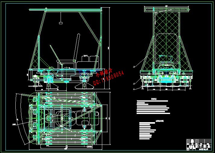
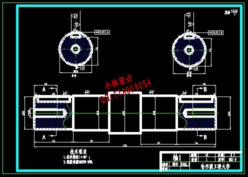
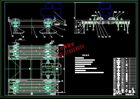
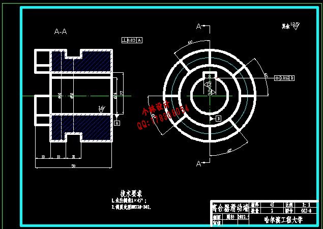
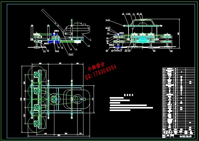
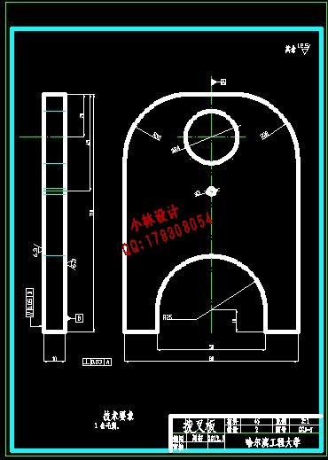
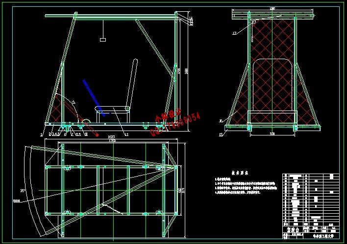
CAD版本图纸,共10张:
题目名称 林区割灌机的结构设计
一、设计目的、意义
割灌机主要用于灌木平茬、幼林抚育、林地清理、草坪修剪以及牧场、果园的割草,装上附件还可以用于抽水及小麦、水稻和玉米的收割,它是一种实用型多用途机具。
随着植树造林的深入,垦区林业已有长足发展,越来越多的人出现在垦区大地上,单靠人工用镰刀抚育管理越来越不适应大面积造林的需要。为了提高工作效率,保证幼林抚育管理任务的完成,必须使割灌机配合工作。实践证明,割灌机应用于林业生产,既能减轻工人的劳动强度,又能按季节连续完成各种林业生产任务,节能低耗,是林业生产上一种省工高效的工具
二、设计内容、技术要求(研究方法)
本设计割灌机,以铁牛-724拖拉机为动力,由动力输出轴系统、传动系统、张紧机构、分株组件、割灌机构、机架、防护和顺料机构组成,重点在于张紧机构、传动机构和割灌机构的设计。
主要技术参数有:
一次割灌宽度:2m
割灌进给速度:0.65m/s(拖拉机1档)
锯片直径:300mm
整机最大离地间隙:400mm
生产效率:4700m2/h.台
液压缸行程:5200mm
三、设计完成后应提交的成果
整机的设计包括:
1、 装配图A0图纸一张;
2、 零件图折合A0图纸二张;
3、 设计说明书(两万字左右)。
四、设计进度安排
2月27日~3月15日,查找相关资料,完成文献综述
3月16日~4月19日,撰写开题报告。初步确定设计总体方案。
4月20日~5月24日,大体完成各部分的设计和绘制装配图和相应零件图。撰写设计说明书
5月25日~6月7日 ,提交正式设计教师审核。
6月8日~6月15日,按照学院的规范要求排版打印设计说明书。上交毕业设计文件准备毕业答辩,参加毕业答辩。
五、主要参考资料
[1] 梁桂清.我国割灌机的现状和发展前景[J].广西机械,2000(1): 24-25.
[2] 许汶祥.新型割灌机的设计研制[J].林业机械与木工设备,2002,30 (2): 10-11.
[3] 刘晋浩,王丹.谈国内外人工林抚育机械的现状及发展趋势[J] .森林工2006,22(3):13-14.
[4] 王燕,王述洋.割灌机械发展现状及趋势[J] .林业机械与木工设备2007,10(35),4-5.
[5] 刘勤,黄晓山,刘易善,刘玉敏,李东玫.2G-200型悬挂式割灌机的研制[J].林业科技,2002,(5).
[6] 陈永康.2GB-081型背负式割滩机的研制[J] .林业机械与木工设备.2002,3:10-11.
[7] 刘冬梅,阮凯林.新型自走式割灌机结构分析[J].林业机械与木工设备2007,12(35),18-19.
[8] Makoto Tanaka,Seiji Sato. FX Series General-Purpose Wire-Cut Electrical-Discharge Machines.
[9] Takamitsu Kimura, Katsunori Sawahata, Takahiro Ssto. Development of High Performance Coated Wice Electrodes for High-Speed Cutting and Accurate Machining.
摘 要
本设计介绍了一种林区割灌机产品:自走式割灌机。设计中根据林区路面状况,以及清林抚育的作业情况,而设计出能够适应林区崎岖路面及道路狭窄等恶劣环境的自走式割灌机,具有很高的实用性和推广价值。
该自走式割灌机由行走部分,割灌部分,驾驶台以及排障部分等组成,可以锯切加工直径范围在10 ~80mm的灌木。整个机器由两个汽油机提供动力,一个提供行走动力,另一个提供割灌动力。锯片位于整个机器的前下端,由驾驶台控制杆控制其离地面高度,以适应林区路面状况。通过顶部的排障杆使高于机器顶部的灌木倒向预定方向,达到排障目的。该自走式割灌机结构简单,容易维修,操作简单。
在文章中,对该自走式割灌机的主要部件进行了设计计算(例如:皮带轮,轴,轴承,键,四连杆等 ),并对主要部件进行了系统的介绍和说明,对使用中涉及到的润滑,保养及注意事项也作了说明。
关键词:自走式;割灌机;割灌部分;行走部分;驾驶台;排障杆
Abstract
A self preceded trash breaker, a new forestry machine has been presented in this paper. According to forest road surface conditions, and working situations of clearing fostering trees, the self-propelled brush breaker was designed to adapt to any atrocious environment, such as rugged road surface, narrowness of road and so on. It was highly practicability and generalizing value.
This self-propelled brush breaker is consist of walking port, cutting port,bridge and breaching of obstacles part and can saw brush in diameter range from 10mm to 80mm.The power of whole machine is supplied by two petrol motors, one is for running power,the other is for breaking brush power. Saw blade was under the machine,the control stick on driving stand control its height away from ground to adapt to the forest road surface condition. The bushes that are higher than the machine can be controlled by a pilot bar, which can make bushes fall along the pre-designed direction and get rid of obstacles. This structure of self-propelled brush breaker is simple, is easy to maintain, and is operated easily as well.
The main parts of the self-propelled brush breaker have been compeered and tested in this paper, such as pulley, axes, bearing, bond,four link rods and so on, and the main parts have been introduced and explained systemically, and have lubrication ,maintenance and other matters n related in using.
Key words:Self-propelled; brush breaker; the cutting port;the walking port;bridge,;pilot bar
目 录
摘要……………………………………………………………………………………………Ⅰ
Abstract……………………………………………………………………………………Ⅱ
第1章绪论……………………………………………………………………………………1
1.1引言……………………………………………………………………………………1
1.2割灌机的应用范围……………………………………………………………………1
1.3割灌机的发展现状……………………………………………………………………2
1.4我国割灌机的市场及前景……………………………………………………………6
1.5割灌机的发展方向……………………………………………………………………7
1.6自走式割灌机设计的意义……………………………………………………………8
第2章 结构概述 ………………………………………………………………………… 9
2.1工作原理……………………………………………………………………………… 9
2.2结构分析……………………………………………………………………………… 9
2.3本章小结…………………………………………………………………………… 10
第3章 行走部分设计…………………………………………………………………… 11
3.1 方案的确定…………………………………………………………………………11
3.2 机构选择……………………………………………………………………………12
3.3 动力选择……………………………………………………………………………13
3.4 主要设计参数………………………………………………………………………13
3.5本章小结……………………………………………………………………………14
第4章 割灌部分设计…………………………………………………………………… 15
4.1 方案的确定…………………………………………………………………………15
4.2 汽油机输出带轮设计 ……………………………………………………………15
4.3 中间传动轴的计算…………………………………………………………………20
4.4 中间传动轴的校核 …………………………………………………………………20
4.5中间传动轴轴承的校核 ……………… ……………………………………………24
4.6 中间轴的键的选择和校核 …………………………………………………………27
4.7本章小结……………………………………………………………………………28
第5章 驾驶台设计………………………………………………………………………29
5.1方案确定……………………………………………………………………………29
5.2本章小结……………………………………………………………………………30
第6章 排障部分设计 …………………………………………………………………31
6.1方案确定……………………………………………………………………………31
6.2本章小结……………………………………………………………………………32
结论……………………………………………………………………………………………33
参考文献……………………………………………………………………………………34
致谢……………………………………………………………………………………………35
|


