|
设计描述:
文档包括:
说明书一份,39页,20000字左右.
开题报告一份.
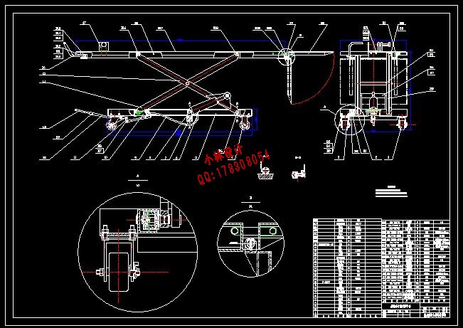
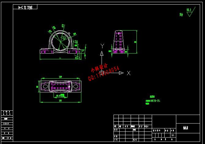
CAD版本图纸,共5张:
I、毕业设计(论文)题目:
摩托车专用升降平台设计
II、毕 业设计(论文)使用的原始资料(数据)及设计技术要求:
已知:额定载重量 500kg 自重≤200kg
850mm ≥升降台最大高度 ≥700mm 升降台最小高度300mm左右
平台尺寸2200×700mm
通过脚踏式液压泵提起货物,要求后轮固定,设置过载安
全阀,确保操作者安全。刹车安全可靠。可在升程内任意位置停止升降。
要求:
1、绘制总装图纸及零件图
2、运动分析
3、总体强度受力分析计算
4、要求成本核算
III、毕 业设计(论文)工作内容及完成时间:
1、开题报告 2周
2、总体设计 2周
3、常规设计 9周
4、成本核算 1周
5、编写毕业设计说明书 2周
6、外文资料翻译 1周
Ⅳ 、主 要参考资料:
1、沈纫秋主编《工程材料与制造工艺教程》北京:航空工业出版社 1991.5
2、机械设计手册 新版 第4卷 液压、气动与液力传动与控制 北京:机械工业出版社
3、曾正明主编 机械工程材料手册(金属材料),第六版,北京:机械工业出版社,2004
4、机械设计手册新版,第4卷.北京:机械工业出版社,2004
5、刘鸿文主编 材料力学Ι,第4版.北京:高等教育出版社,2006
6、须雷 升降机的现代设计方法[J].起重运输机械,1996(8):3~8
7、王昆等 机械设计(机械设计基础)课程设计.高等教育出版社,2006
8、Purdum.T. Machine Design[M]. Journal of Science & Engineering,1998
摩托车专用升降平台设计
摘要: 升降台的种类很多,按照升降结构的不同,可分为剪叉式升降台、升缩式升降台、套筒式升降台、升缩臂式升降台及折臂式升降台等。液压升降台采用液压驱动,整机由主机、液压系统、控制系统组成。
本文所介绍的摩托车专用升降台最大载重量是500kg,它有两部分组成:剪叉机构和液压系统。剪叉机构的操作控制是由脚踏式液压泵和液压缸来完成的。这样的液压升降台的设计通常根据设计参数要求,粗略估算剪叉尺寸,然后求出液压缸推力,从而进行液压缸选型。由于液压缸的尺寸及摆放的位置不同,设计当中可能会产生干涉。解决的办法是通过对机构中三种液压缸布置方式的分析和比较,确立一种方案,并根据需要,设计最优的剪叉机构,及对连接零件、滑动装置的选型等。在满足机构设计的基础上,对受力较大的机构进行强度和刚度的校核,检验是否满足设计要求。作为控制系统,液压系统的设计很重要,这包括回路保压设计,液压泵的选取及其他元件的选型等。最终完成摩托车专用升降台的设计。本设计借鉴了相关的资料,采用了相关的标准,充分的吸收了前人的宝贵的经验。
关键词:升降台,液压系统,剪叉机构,脚踏式液压泵,液压缸
THE DESIGN OF THE LIFT TABLE
RESERVED FOR MOTOR BICYCLE
Abstract : There are many types of lift table, according to the structure of the different movements ,which can be divided into scissors-lifts or shrink-lifts ,sleeve-lifts or shrink arm lifts and arm –folding lifts and so on . The hydraulic pressure actuation is used in hydraulic pressure lift table, and the whole machine was made of the main body, the hydraulic system and the control system.
Maximal load capacity of hydraulic press described by this paper is 500 kg , it has two parts: this scissors fork and hydraulic pressure system. This operation of the scissors fork is under the control of foot-operated hydraulic pump and hydraulic cylinder.Such hydraulic lifts are usually designed in accordance with the requirements of the design parameters, then the hydraulic cylinder thrust force is extracted by the sketchy estimate size.Thus the typle of the hydraulic cylinder can be sure. As the size of hydraulic cylinders and the positions for securing are different, it possibly have the interference in the design. The solution is to establish a programe through the analysis and comparison in the hydraulic cylinder layout.According to the need, we can design the optimal scissors fork, and select the connector of parts, sliding devices and so on. In the foundation of the design,the intensity and the rigidity examination to the large stress organization should bemade to examine whether that satisfy the design requirements. As the control system, hydraulic system's design is very important, including the design of the return route for guarantee presses, hydraulic pump's selection and other part's shaping and so on. In the entire process, the floor fluctuation and the turn over complete by hydraulic cylinder's expansion.Finally,the design of the lift table reserved for motor bicycle is completed.The design draws lessons from the pertinent data, has adopt the pertinent standard,and admit sufficiently the prehominid precious experience.
Keywords: lift table, hydraulic system, scissors fork mechanism, foot-operated hydraulic pump, hydraulic cylinder
目 录
1 绪论
1.1 升降台的发展现状......................................... (1)
1.2 升降台的发展前景......................................... (1)
1.3 摩托车升降台的设计特点................................... (2)
1.4 摩托车升降台的安全要求................................... (2)
1.4.1设计的安全要求.......................................... (2)
1.4.2其他安全要求............................................ (3)
2 摩托车升降台的总体设计
2.1 设计参数及要求............................................ (4)
2.2 摩托车升降台机构设计时应注意的问题........................ (4)
2.3 摩托车升降台的两种结构形式................................ (4)
2.4 摩托车升降台机构中三种液压缸布置方式的分析比较............ (5)
2.4.1问题的提出.............................................. (5)
2.4.2三种方案的分析和比较.................................... (5)
2.5 总体方案确定及总体设计.................................... (7)
3 摩托车专用升降台的受力分析计算
3.1 实例分析.................................................. (8)
3.1.1摩托车专用升降台的结构简化.............................. (8)
3.1.2升降台受力分析.......................................... (8)
3.2 实例计算................................................. (12)
3.2.1剪叉臂长度及液压缸安装位置的确定....................... (12)
3.2.2液压缸推力的计算及选型................................. (14)
3.2.3其他力的计算........................................... (15)
4 各参数及结构设计
4.1 升降台主要零部件材料的选择............................... (17)
4.1.1底座材料的选择......................................... (17)
4.1.2 液压缸缸体尾部横梁的材料选择........................... (17)
4.1.3搭板的材料选择......................................... (17)
4.1.4工作台的材料选择....................................... (17)
4.2 内外剪叉臂与底架连接的销轴结构设计....................... (18)
4.3 轴套的结构设计........................................... (18)
4.4 滚轮的结构设计........................................... (18)
4.5 脚轮的选型............................................... (19)
5 液压系统的分析与设计
5.1 负载分析................................................. (20)
5.2 液压系统方案设计......................................... (20)
6 液压系统的参数计算与元件选择
6.1 液压泵的选择............................................. (21)
6.1.1液压泵压力的计算....................................... (21)
6.1.2液压泵的选择........................................... (21)
6.2 液压缸作用时间的计算..................................... (21)
6.3 油管的选择............................................... (22)
7 强度校核
7.1 剪叉臂的强度校核......................................... (23)
7.2 液压缸底架固定横梁的强度校核............................. (25)
7.3 轴的强度校核............................................. (28)
7.3.1内剪叉臂固定端销轴的强度校核........................... (28)
7.3.2液压缸缸体尾部销轴的强度校核........................... (28)
7.3.3液压缸活塞杆头部支撑轴的强度校核....................... (29)
8 校核
8.1 重量核算................................................. (30)
8.2 成本核算................................................. (30)
8.2.1成本的概念............................................. (30)
8.2.2产品生产成本项目....................................... (31)
8.2.3生产成本的核算......................................... (31)
9 结论........................................................(33)
参考文献...................................................... (34)
致谢........................................................... (35)
附录 A........................................................ (36)
| 


