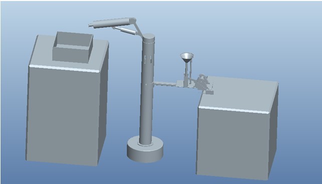
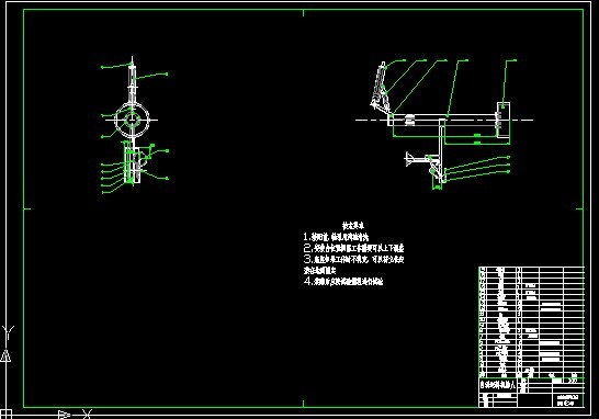
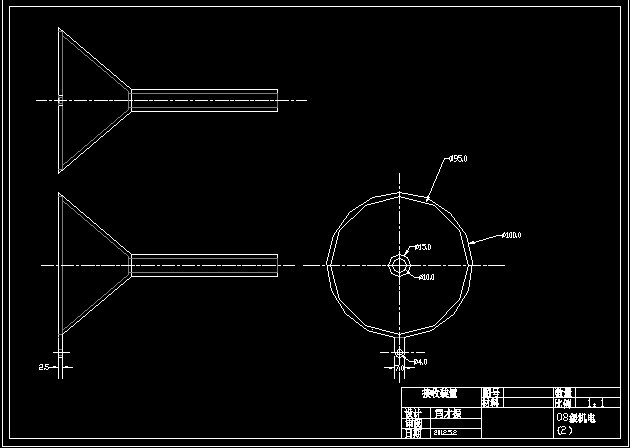
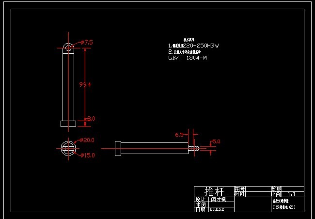
设计描述:
文档包括:
Word说明书1份,共35页,约16000字
CAD版本图纸,共3张
PROE三维一套
双臂式自动送料机器人结构设计
摘要;
铆接技术作为金属结构零件相互连接的方法,适用于铆钉连接、零件翻边、永久连接等,在五金工具、飞机制造维修、精密机械、汽车制造等行中应用广泛。本课题通过了解压铆机的工作原理及主要功能,分析目前常用送铆方式,提出双臂自动送铆机器人的自动送铆方案。中一臂主要为物料的抓取功能;另一臂主要完成送料功能。
本文根据系统功能,设计各机构的结构形式;根据设计要求,确定设计参数。并且用三维软件进行三维实体建模,实现了运动仿真。这种双臂送料机构将克服普通送料机构的弊端,大大提高自动送料机构的生产效率,减少劳动成本,提高人身安全,保障生产质量。
关键词:铆接;自动送料;机器人
Design of Structure about
Arm Type Automatic Feeding Robot
Abstract:
Riveting as metal structural parts interconnected, has wildly used in rivet connection parts flanging, permanent connections, hardware and tools, aircraft manufacturing, maintenance, precision machinery, automobile manufacturing line and so on.Through extracting riveting machine works and the main function analysis commonly used to send riveting, the subject raise his arms to automatically send the automatic feed riveting riveting robot. One arm realize the function of materials crawl, the other arm to complete the feeding function.
Based on system functionality, the structure of the agencies is designed according to design requirements, determine the design parameters. And by the use of 3D software, 3D solid modeling realize motion simulation. Such arms feed mechanism overcome the drawbacks of the ordinary feed mechanism and greatly improve the production efficiency of automatic feed mechanism, reduce labor costs, improve personal safety and protect the quality of production.
Key words:Rivet;Automatic Feed;Robots
目 录
第一章 绪论 1
1.1 选题的目的意义 1
1.2 本课题在国内外的研究状况及发展趋势 1
1.3 常用自动送料方式 2
1.3.1采用双作用缸实现物料的分离功能和定位夹紧功能的自动送料 2
1.3.2利用机械手进行送料 2
1.3.3采用伺服电机控制工作台进行送料 2
1.4 本课题主要研究内容及设计任务 2
第二章 对课题的分析 4
2.1 现在企业的要求 4
2.2 两种典型的送料机构 4
2.2.1 气动送料机 4
2.2.2 利用机械手自动送料 5
2.3 本课题采用送料方式及其创新 7
第三章 双臂式自动送料机器人原理分析及计算 8
3.1 液压缸的原理和计算 8
3.1.1 主要尺寸的计算 8
3.1.2 强度校核 9
3.1.3 活塞杆稳定性校核 9
3.2 电磁吸附手原理及计算 10
3.2.1 基本公式和一般概念 10
3.2.2 参数计算过程 14
3.3 立柱的尺寸计算 16
3.4 驱动电机的选择 18
3.4.1 直流电机与步进电机比较 18
3.4.2 步进电机的选择 18
3.5 螺钉的选择 19
第四章 实体设计 22
4.1 设计软件介绍 22
4.2 液压缸结构的设计 23
4.3 取料手结构的设计 23
4.4 立柱的设计 24
4.5 M6螺母接收装置设计 25
4.6 螺母摆正槽设计 26
4.7 送料机构设计 27
4.8 整体装配图 28
第五章 设计总结 29
致谢 31
参考文献 32
附录 33
|