|
设计描述:
文档包括:
word版设计说明书一份,共30页,约14000字
CAD版本图纸,共12张
目 录
1前 言 1
1.1 本课题的意义 1
1.2 国内发展概况 1
1.3 课题由来及所需基本条件 2
2组合机床总体设计 3
2.1 总体方案论证 3
2.1.1 加工内容及要求 3
2.1.2 机床配置型式的选择 3
2.1.3 定位基准的选择 3
2.1.4 滑台型式的选择 4
2.2 确定切削用量及选择刀具 4
2.2.1 切削用量的选择 4
2.2.2 计算切削力、切削扭矩及切削功率 5
2.2.3 刀具结构的选择 5
2.3 总体设计—“三图一卡” 6
2.3.1 被加工零件工序图 6
2.3.2 加工示意图 6
2.3.3 机床尺寸联系总图 7
2.3.4 机床生产率计算卡 9
3 组合机床夹具设计 12
3.1 夹具设计的基本要求和步骤 12
3.1.1 夹具设计的基本要求 12
3.1.2 夹具设计的步骤 12
3.2 定位方案的确定 13
3.2.1 零件的工艺性分析 13
3.2.2 定位方案论证 13
3.2.3 误差分析 13
3.2.4 校核加工精度 15
3.3导向装置 15
3.4 夹紧方案的确定 16
3.4.1 夹紧装置的确定 16
3.4.2 夹紧力的确定 18
3.4.3 气缸的选择 19
3.5 夹具体的设计 20
3.6 夹具三维设计 20
3.6.1 三维建模及三维软件介绍 20
3.6.2 基于三维的夹具设计过程 21
4 结论 24
参 考 文 献 25
致 谢 26
附 件 清 单 27
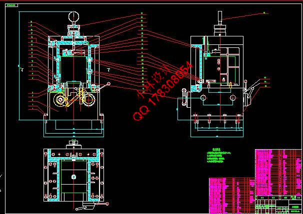
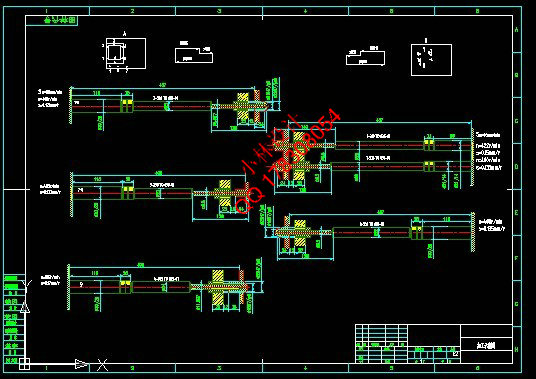
变速箱壳体组合机床的夹具设计
摘 要:变速箱壳体组合机床采用卧式双面加工方案。用于钻削被加工零件左侧面上的8个∅8.5的孔,1个∅11.9的孔,右侧6个∅8.5的孔,2个∅9.8的孔。主要包括总体设计和夹具设计两个部分。左侧主轴箱用来加工这9个孔,右侧主轴箱用来完成剩下的8个孔的加工,两主轴箱的中间是夹具部分。机床采用液压滑台实现刀具的进给,以保证进给速度的稳定可靠。工件选用“一面两孔”的定位方案,能够保证工件的位置精度要求,同时便于工件装夹,又有利于夹具的设计与制造。采用气压夹紧方式。为保证工件上被加工孔的位置精度,采用了导向装置。因工件批量较大,导向装置中的钻套容易磨损,所以采用了可换钻套。夹具体材料采用HT150,并在夹具体上开设排屑槽以防止切屑在定位元件工作表面上或其他装置中堆积而影响工件的正确定位和夹具的正常工作。
关键词:组合机床;总体设计;夹具
The fixture design of modular machine tool for transmission body based on 3D method
Abstract: The modular machine tool for transmission body uses the horizontal-type and two-side processing plan.It is used for drilling these holes in the work piece: eight holes with the diameter 8.5mm and depth 24mm, one hole with the diameter 11.9mm and depth 25mm on the left side,six diameter 8.5m holes and their bottom surfaces on the right surface, two diameter 9.8mm holes.The topic includes two parts, the general design and fixture design of the machine tool. The left spindle box is used for machining nine tappet holes, the right spindle box is used for machining eight holes, and a fixture is between two spindle boxes.To achieve stable and reliable feed, hydraulic pressure sliding tables are used in this machining tool.The work piece is located at the fixture through "a face two holes",which can ensure the position precision needs of the work piece and be beneficial to design the fixture.The combination machine is clamped by atmospheric pressure devices.To ensure position precision, the guiding devices are used. Replaceable guiding sleeves are chosen, because they are easy wearing in large quantities of production. The material of clamp body is HT150. Chip troughs which are in the clamp body are free of chip falling onto the working surface of positioning components or accumulating on other devices, and ensure the work piece correct positioning and the fixture normal working.
Key words: combination machine; design; fixture
|