 |
 |
|


|
设计名称 |
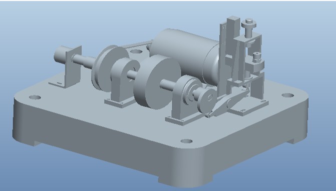
高速凸轮机构动力学试验平台研制[Proe三维] |
 |
|
设计编号 |
Z066 | |
|
设计软件 |
AutoCAD, Word | |
|
包含内容 |
见右侧图片 | |
|
说明字数 |
14000字 | |
|
图纸数量 |
见右侧图片 | |
|
推荐指数 |
较高 | |
|
价格: |
价格优惠中 | |
|
整理日期 |
2013.9.26 | |
|
整理人 |
小林 | |
|
购买流程 |
<查看如何购买本站设计> |
|
设计简介 |
设计描述:
文档包括:
CAD版本图纸,共16张 摘 要 凸轮从动件系统在各个领域如纺织机械、包装机与食品机械、自动化工业、印刷行业、内燃机、农业 机具都广泛被应用。在一般情况下它被认为是刚性系统。但随着机械效率的提高,凸轮转速随之上升 ,因而产生了较大的弹性变形。从动件运动规律大大偏离了理论值。因此对凸轮从动件系统先进行测
试是很重要的。 弹簧,并在不同转速下进行实验。在试验台一定位置安装相应的传感器,测试出在不同条件下他们的 真实运动规律,从而了解各种影响因素对它们的影响。由于没有进行实验,本文对高速凸轮系统进行
了一定的动力学建模分析。 Abstract Cam follower system in various fields such as textile machinery, packaging machine and food machinery, automation industry, printing industry, internal combustion engines, agricultural machinery are widely applied. Under normal circumstances it is considered to be a rigid system. But with the mechanical efficiency, the cam speed rise, thus creating a greater elastic deformation. Follower motion rule greatly deviated from the
theoretical value. Therefore tested against the cam follower system is very important.
for several impact factors. experiment, different rigidity of the swing lever, the type of use to compress the springs, and experiments at different speeds. Install the appropriate sensors, a certain position in the test rig to test out their true law of motion under different conditions, to understand the impact of various factors affecting them. In the absence of experimental, high-speed cam system dynamics modeling. Key words: high-speed cam;sensing element;test bench;dynamic modeling
择......................................................................................
.................................12 择......................................................................................
.....................................13 计......................................................................................
.................................16 计......................................................................................
.................................20 立......................................................................................
.........................21 |
|
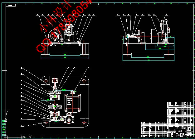
部分图纸 截图 |
   |
|
说明: |
如需了解本设计的具体详细信息请联系本站客服,说明看哪个设计(编号)哪个详细部分,我们将远程或截图给您观看. 机械毕业设计|论文 |

| [要求PR≥2,百度收录≥1000页;联系QQ:178308054] |
Powered by 小林机械资料商城 © 2013-2020 All Rights Reserved. 客服QQ:178308054
喜欢www.xiaolinbysj.com,请告诉你QQ上的5位好友,多谢您的支持! 皖ICP备2021006205号-1
