|
设计描述:
文档包括:
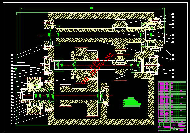
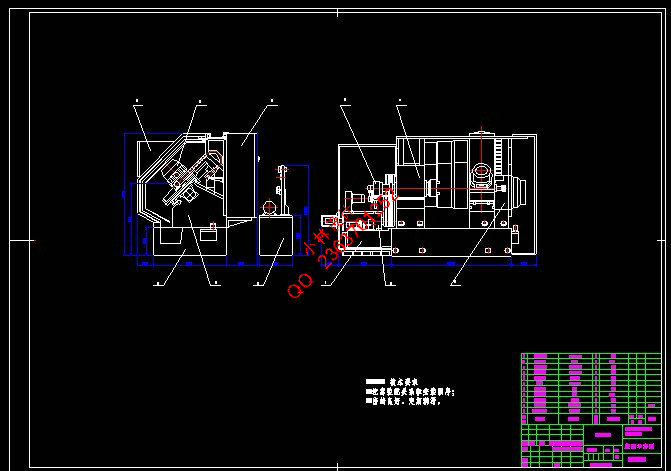
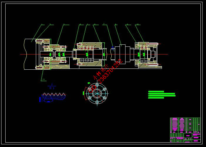
word说明书一份,共72页,约22000字
CAD版本图纸,共4张
摘 要
2l世纪,随着计算机技术的快速发展,数控机床在机械工业中的应用比例逐渐增大,其中数控车床的应用最为广泛。数控车床与普通车床相比,在提高生产减轻工人劳动强度、降低生产成本和增加效益方面都有其优越性。因此,设计一种功能全面、操作方便、安全可靠、价格经济的数控车床具有重要意义。
本文主要从经济实用上对数控车床的总体机械结构进行了设计。电动机通过变速箱与主轴进行联接,使主轴的功率、扭矩特性和电机的功率扭矩特性相匹配,这样适用范围就更宽,在使用方面也容易控制。为使数控车床具有更好的定位精度,本系统采用半闭环伺服系统。
设计不仅对横向进给系统,纵向进给系统进行了设计和详细计算。还对数控系统、导轨的设计、液压传动以及润滑与冷却系统进行了阐述。
关键词:数控车床;电动机;调速箱;轴;定位精度
Abstract
21st century, with the fast development of computer technology, CNCmachine tools are enlarged in application proportion among mechanical industry, among which the numerical control lathe is the most popularapplication. Comparing with ordinary lathe, the numerical control lathe has its superiority in boosting productivity, lightening worker's labor intensity, reducing the production cost and increasing benefit. Therefore, it is meaningful to design a kind of numericai control late with overall functions, safe and reliable, price economy easy to operate.
The overall inechanical structure of numerical control late has been
designed in this paper, mainly from economy and practical value. The motor
is linked to spindle, making power and torsion characteristic of match to torsion characteristic power of the electrical machinery. In this case the scope of application is wider and it is easy to control during machining. In order to make the numerical control lathe have the better precision of localization, this system adopts servo system the half-closed loop.
Horizontal feed system and vertical feed system are designed and
calculated in details in this design. In addition, numerical control system, guide-design, hydraulic transmission, lubrication and cooling system are expounde.
Keyword:numerically controlled lathe;the transmission;shaft;Positioning accuracy
目 录
摘 要 I
Abstract II
第1章 绪论 1
1.1 数控技术 1
1.1.1 数字控制 1
1.1.2 数控机床 1
1.1.3 数控系统 1
1.1.4 数控程序 1
1.1.5 数控编程 1
1.1.6 数控加工 2
1.2 数控机床的产生和发展 2
1.3 我国数控技术发展概况 3
1.4 数控机床的特点及适用范围 4
1.4.1 数控机床的特点 4
1.4.2 数控机床的适用范围 4
1.5 数控车床的分类 5
1.6 简易数控车床的特点 5
第2章 数控车床的总体方案设计 6
2.1 数控车床的组成 6
2.2 工艺范围的确定 6
2.3 数控车床的安全防护 6
2.3.1 热变形的防止 6
2.3.2 噪声的防止 6
2.3.3 振动的防止 7
2.4 基本参数的确定 7
2.4.1 主参数和尺寸参数 7
2.4.2 运动参数的确定 7
2.4.3 动力参数 8
第3章 机床主传动系统设计 11
3.1 主传动方案 11
3.2 主轴转速的确定 11
3.2.1 计算主轴转速 11
3.2.2 计算主轴的变速范围 12
3.3 传动轴转速的确定 12
3.4 变速箱的设计 12
3.4.1 选取变速箱公比 12
3.4.2 计算变速箱的变速级数 12
3.4.3 分级变速箱转速图的绘制 13
3.5 主传动系统结构设计及校核 13
3.5.1 带传动的结构设计 13
3.5.2 Ⅰ轴上的齿轮结构设计及校核 15
3.5.3 Ⅱ轴上齿轮的结构设计 21
第4章 机床主轴部件设计 23
4.1 主轴组件的设计 23
4.1.1 对主轴组件的基本要求 23
4.1.2 主轴参数的确定 24
4.1.3 轴承的选择及校核 25
4.1.4 主轴的结构设计预校核 27
4.2 传动轴的设计 30
4.2.1 传动轴应满足的要求 30
4.2.2 传动轴的材料和构造 30
4.2.3 轴径的确定和轴承的选择 31
第5章 伺服进给传动系统设计 32
5.1 伺服进给系统的设计要求 32
5.1.1 纵向进给系统传动方案 32
5.1.2 横向进给系统方案 32
5.2 伺服进给系统的设计要求 33
5.2.1 稳定性 33
5.2.2 精度 33
5.2.3 快速响应性 33
5.3 纵向进给系统的设计 33
5.3.1 主要工作条件的确定 33
5.3.2 传动系统设计 33
5.3.3 滚珠丝杠的选择 34
5.3.4 丝杠支撑方式的选择 35
5.3.5 选择伺服电动机 35
5.3.6 伺服系统增益 36
5.3.7 精度验算 37
5.4 横向进给系统的设计 39
5.4.1 主要工作条件的确定 39
5.4.2 传动系统设计 39
5.4.3 滚珠丝杠的选择 40
5.4.4 丝杠支承方式的选择 40
5.4.5 选择伺服电动机 41
5.4.6 伺服系统增益 42
5.4.7 精度验算 43
5.4.8 同步齿形带的设计计算 44
第6章 机床总体结构与布局 47
6.1 机床床身结构 47
6.1.1 对床身结构的基本要求 47
6.1.2 床身的结构 47
6.2 机床导轨的选择 48
6.2.1 导轨的作用 48
6.2.2 导轨应满足的要求 48
6.2.3 导轨的主要失效形式 48
6.2.4 选择导轨 49
6.3 支承件的选择 49
6.3.1 支承件的功用 49
6.3.2 支承件的基本要求 49
6.3.3 支承件的静刚度 50
6.3.4 支承件的动态特性 50
第7章 液压传动 52
7.1 数控车床的液压系统及应用 52
7.1.1 卡盘动作的控制 53
7.1.2 回转刀架动作的控制 53
7.1.3 尾座套筒动作的控制 53
7.2 滑移齿轮的液压传动 54
7.2.1 确定工作要求 54
7.2.2 负载 54
7.2.3 确定液压缸主参数 54
第8章 润滑与冷却系统设计 56
8.1 润滑系统设计 56
8.1.1 主轴组件的润滑 56
8.1.2 导轨及滚珠丝杠的润滑 56
8.2 冷却系统设计 56
8.2.1 冷却系统的基本组成 59
8.2.2 冷却液及冷却装置的选择 59
结论 59
致谢 60
参考文献 61
| 


