 |
 |
|


|
设计名称 |
基于DSP电机控制方法研究 |
 |
|
设计编号 |
V096 | |
|
设计软件 |
AutoCAD, Word | |
|
包含内容 |
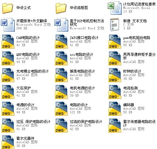
见右侧图片 | |
|
说明字数 |
20000字 | |
|
图纸数量 |
见右侧图片 | |
|
推荐指数 |
较高 | |
|
价格: |
价格优惠中 | |
|
整理日期 |
2013.09.26 | |
|
整理人 |
小林 | |
|
购买流程 |
<查看如何购买本站设计> |
|
设计简介 |
设计描述:
文档包括: CAD版本图纸,共19张
高,DSP数字化处理能力也得到了质的飞跃。所以学会应用DSP时非常重要的。
方案,本文采用PID控制方法来控制电机,详细介绍了PID控制算法。 路的设计,PWM光电耦合隔离电路的设计,电流的采样电路的设计,对DSP进行保护电路的保护电路的设计等
。 初始化,SCI模块的初始化,以及对数字滤波进行编程。
关键词:DSP;CCS;PWM;无刷直流伺服电机 development of digital control is higher and higher, The ability of digital handle has own a
qualitative leap.So learn to apply DSP is very important. mathematical model of the star connection. I designed the general planning of digital control the brushless DC servo motor, this paper adopts the PID control method to control the motor and
introduces the PID control in detail. based on TMS320F2812 .I designed the DSP power supply. I designed the drive circuit and the PWM photoelectric coupling isolation circuit.I also designed the sampling circuit and the current
of protection .At last I designed the protection circuit. completed the initialization of system,the initialization of encoder module , the initialization of capture module ,the initialization of SCI module , and programming of the digital filter.
Keywords: DSP; CCS; PWM; brushless DC servo motor |
|
部分图纸 截图 |
|
说明: |
如需了解本设计的具体详细信息请联系本站客服,说明看哪个设计(编号)哪个详细部分,我们将远程或截图给您观看. 机械毕业设计|论文 |

| [要求PR≥2,百度收录≥1000页;联系QQ:178308054] |
Powered by 小林机械资料商城 © 2013-2020 All Rights Reserved. 客服QQ:178308054
喜欢www.xiaolinbysj.com,请告诉你QQ上的5位好友,多谢您的支持! 皖ICP备2021006205号-1
