 |
 |
|


|
设计名称 |
机械手结构的总体方案设计 |
 |
|
设计编号 |
G187 | |
|
设计软件 |
AutoCAD, Word | |
|
包含内容 |
见右侧图片 | |
|
说明字数 |
21000字 | |
|
图纸数量 |
见右侧图片 | |
|
推荐指数 |
较高 | |
|
价格: |
价格优惠中 | |
|
整理日期 |
2013.9.26 | |
|
整理人 |
小林 | |
|
购买流程 |
<查看如何购买本站设计> |
|
设计简介 |
设计描述:
文档包括: 摘 要
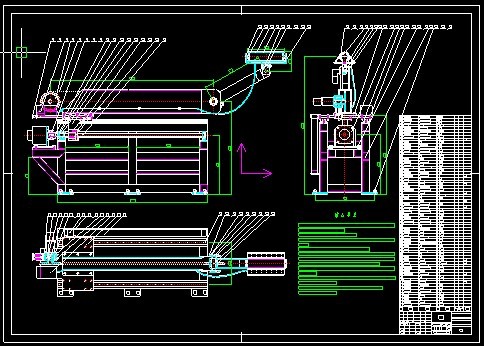
随着机器人在各个领域应用的日益广泛,许多场合要求机器人具有力控制的能力。此次设计是针对回转壳体内自动粘贴胶片的任务,设计一个3—DOF平面关节型机械手(包括1个移动关节,2个转动关节和末端执行机构),配合壳体驱动系统来实现此任务。在机械手工作过程中,通过伺服电机带动丝杠转动,从而来完成机械手水平方向的移动,旋转关节1通过链传动来完成平面内的旋转动作,旋转关节2直接在伺服电机的驱动下完成平面内的旋转动作,这样机械手可以伸入口径较小的回转壳体内完成粘贴胶片的任务。 关键词:机械手;自由度;运动学分析;伺服电机;直角减速器
With the increasing application of robot in various industrial fields, it is requested that robot has the ability to control power. According to the contact task of rotary hull, a 3-DOF robot manipulator is designed in order to accomplish sticking of the colloid. The robot manipulator consists of a transfer joint and two revolute joints and robot end-effector. The robot manipulator could realize the contacting task combining with the driving system of rotary hull. The concrete processing comprising of driving screw transmission with the servo motor. In this way, robot manipulator could complete movement in horizontal direction, the revolute joint could be able to accomplish revolute motion of two dimension-space through a chain driving, the revolute joint of end-effector completes directly revolute motion with the servo motor.
Keywords: Robot manipulator;Freedom;Kinematics analysis;Servo motor;Right-angle reducer |
|
部分图纸 截图 |
    |
|
说明: |
如需了解本设计的具体详细信息请联系本站客服,说明看哪个设计(编号)哪个详细部分,我们将远程或截图给您观看. 机械毕业设计|论文 |

| [要求PR≥2,百度收录≥1000页;联系QQ:178308054] |
Powered by 小林机械资料商城 © 2013-2020 All Rights Reserved. 客服QQ:178308054
喜欢www.xiaolinbysj.com,请告诉你QQ上的5位好友,多谢您的支持! 皖ICP备2021006205号-1
