|
设计简介 |
设计描述:
文档包括:
WORD版设计说明书1份,共52页,约16000字
任务书一份
开题报告一份
外文翻译一份
CAD版本图纸,共3张
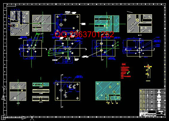
立卧式组合机床液压系统设计
摘 要
本文主要阐述了立卧式组合机床液压系统设计,通过组合机床动力滑台液压系统的工况分析、确定液压系统主要参数、制定基本方案,拟定液压系统原理图、液压元件的选择以及系统性能验算、绘制工程图,编制技术文件。熟悉机床液压系统的设计方法和设计步骤,使机床依次实现工件定位、夹紧、快进、工进、停留、快速退回等待下次加工等动作。设计出结构简单、工作可靠、成本低、效率高、操作简单、维修方便的液压传动系统。
本系统采用一台液压泵向多个液压缸供油,当系统对流量的需求量变化较大时,采用蓄能器增速回路,可减少系统的功率损失和发热。立卧式组合机床液压系统是用来控制液压动力滑台的,通过控制动力滑台来实现组合机床的各个动作从而完成工件的加工。本液压系统中有五个液压缸,其中两个为工作进给缸,一个定位缸,一个夹紧缸和一个输送缸。该系统中采用标准液压动力滑台,自动化程度高,定位、夹紧均有液压系统实现,进行工进立、卧滑台也可同时实现工作循环。满足各工位快进、工进、快退之间互不干涉的要求。采用进口节流加背压的调速方法,顺序背压阀在快进时只形成很小的背压,功率损失小;工进时该阀能自动的使背压加大,进给速度平稳。通过与电气系统的配合,可自动完成设计要求全部动作。
关 键 词:组合机床,动力滑台,液压系统,泵,蓄能器
VERTICAL AND HORIZONTAL COMBINATION MACHINE HYDRAULIC SYSTEM DESIGN
ABSTRACT
This thesis describes the combination of vertical and horizontal hydraulic system design,power sliding through a combination of machine tool hydraulic systems working condition analysis to determine the main parameters of the hydraulic system, the development of the basic program, developed hydraulic system diagram, hydraulic component selection and system performance checking, drawing engineering drawings and technical documents. Familiar with hydraulic system design methods and design steps, so that the machine in order to achieve workpiece positioning, clamping, fast forward, work into, stay, quickly returned to wait for the next processing and other activities. Design a simple structure, reliable operation, low cost, high efficiency, simple operation, easy maintenance, hydraulic drive system.
The system uses a hydraulic pump to a plurality of hydraulic cylinder oil, and when large changes of the flow demand, the use of growth accumulator circuit, the system can reduce the power loss and heat. Combination of vertical and horizontal hydraulic system is used to control the hydraulic power sliding table, by controlling the power slider to achieve the combination of the various actions in order to complete the machine workpieces. The hydraulic system has five cylinders, two of which work feeding cylinder, a positioning cylinder, a clamping cylinder and a delivery cylinder. The system uses standard hydraulic power slide, high degree of automation, positioning, clamping hydraulic systems were implemented for workers into the vertical, horizontal sliding table can simultaneously achieve work cycle. Fast forward to meet each station, work forward, rewind, mutual non-interference between the requirements. Imported throttling back pressure of the speed control method, the order in fast forward back pressure valve formed only a small back pressure, the power loss is small; work into the valve can automatically when the back pressure increased, the feed rate steady . Through the cooperation with the electrical system, the design requirements can be done automatically all the action.
KEY WORDS: Combined Machine Tools,Power Sliding Feed Table,Hydraulic System,Pump,accumulator
符号说明
符 号 单 位 意 义
M 牛.米 弯矩
Ft 牛 轴向切削力
F 牛 力
n 转每分 转速
d 毫米 直径
v 米每秒 速度
f 转每毫米 进给量
L 毫米 长度
P 千瓦 功率
T 牛.米 扭矩
q 升每分 流量
p 帕 压力
t 秒 时间
D卧 毫米 卧式动力滑台液压缸活塞杆外径
D立 毫米 立式动力滑台液压缸活塞杆外径
L 毫米 组合机床行程
V 毫升每转 液压泵的排量
P 瓦特 系统功率
系统效率
n 转每分 转述
目 录
前 言 1
第1章 液压系统工况分析 3
§1.1理论依据、设计方法和研究步骤 3
§1.2立卧式组合机床的工作原理 3
§1.2.1机床的主要运动 3
§1.2.2动力滑台的特性 4
§1.3组合机床动力滑台液压系统的使用要求及负载分析 4
第2章 方案分析及液压原理图的拟定 6
§2.1立卧式动力滑台工作要求 6
§2.2计算液压缸的外负载、绘制工作循环图 6
§2.3计算液压缸外负载,绘制工作循环图 6
§2.3.1动力滑台轴向切削力的计算 6
§2.3.2计算液压缸外负载、绘制工作循环图 8
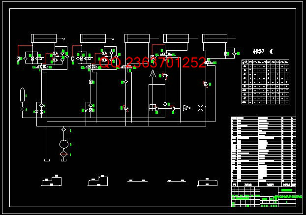
§2.4拟定液压系统方案、绘制液压系统原理图 9
§2.4.1拟定液压系统方案、绘制液压系统原理 9
§2.4.2绘制液压系统图 13
§2.4.3该系统工作原理分析 15
第3章 元件的参数计算与选择 17
§3.1确定液压缸的主要参数 17
§3.1.1初选液压缸的工作压力 17
§3.1.2确定液压缸的主要结构参数 17
§3.2 计算卧式动力滑台液压缸的工作压力和输入功率 18
§3.2.1计算卧式动力滑台液压缸的工作压力 18
§3.2.2计算液压缸的输入功率 19
§3.3 设计计算立式动力滑台液压缸 20
§3.3.1选取工作压力及背压力 20
§3.3.2确定液压缸结构尺寸 20
§3.3.3认证液压缸筒壁厚 20
§3.3.4定液压缸筒的长度 21
§3.3.5校核活塞杆的稳定性 21
§3.3.6液压缸各截面积 22
§3.3.7初定液压缸流量 22
§3.3.8计算液压缸的输入功率 22
§3.4 选择液压泵 23
§3.4.1液压泵工作压力、流量、驱动功率计算 23
§3.5蓄能器的选择 24
§3.6选择液压阀 25
§3.6调整各阀的参数 26
§3.6.1流量阀各参数的调定 26
§3.6.2压力阀参数的调定 27
§3.6.3其他阀压力参数的调定 28
§3.6.4油管的尺寸 29
第4章 集成块的设计 30
§4.1 集成块简介 30
§4.2 集成块的设计原则 30
§4.3 集成块的结构设计 31
§4.4 集成块装配与调试 32
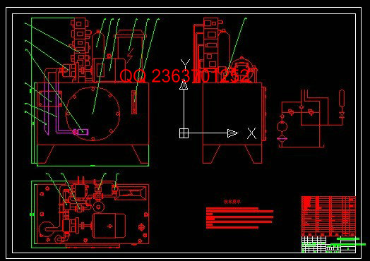
第5章 油箱的设计 33
§5.1确定油箱容量 33
§5.2油箱的结构设计 33
第6章 系统稳定性验算 37
§6.1液压泵工作压力稳定性校核 37
§6.2系统热能工况的稳定性校核 39
§6.2.1系统效率 39
§5.2.2系统热能工况的稳定性校核 39
结 论 41
参考文献 42
致 谢 44
|