|
设计简介 |
设计描述:
文档包括:
Word版设计说明书1份,共35页,约12000字
任务书一份
CAD版本图纸,共12张
摘 要
碾压式切管机的设计是一项技术革新项目。切管机主要用于车辆,工业或建材生产中的批量下料工作,用于切割 的金属管。它的特点是工作平稳、连续、效率高、劳动强度低、能保证尺寸精确度的要求,适应于在各种环境下的连续工作。
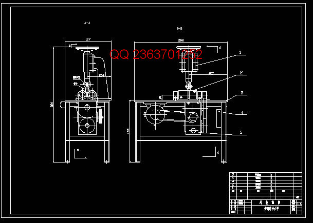
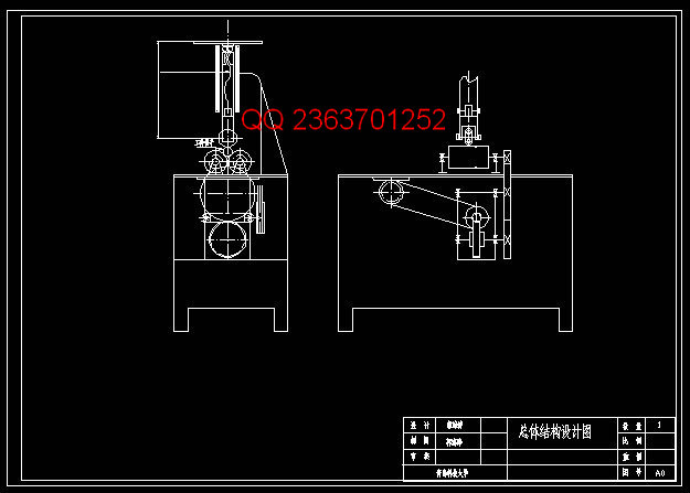
碾压式切管机的工用原理是:由电动机经V带传动,蜗轮减速箱、开式齿轮传动到一对滚子,从而带动(金属管)的旋转,实现切割时的主运动。与此同时,操纵手轮,通过螺旋传动,将圆盘刀片向下移动进给,并在不断增加刀片对管子的压力过程中,实现管子的切割工作。
原始数据:滚子的转速为 =70转/分,驱动电动机的型号选择JO2-22-4,其额定功率为 =1.5千瓦,满载转速 =1410转/分 ,切管直径D为3/8〞~
4〞
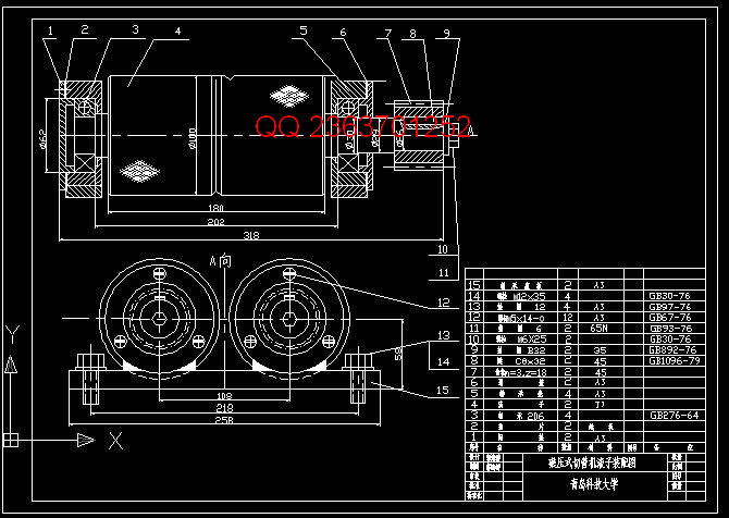
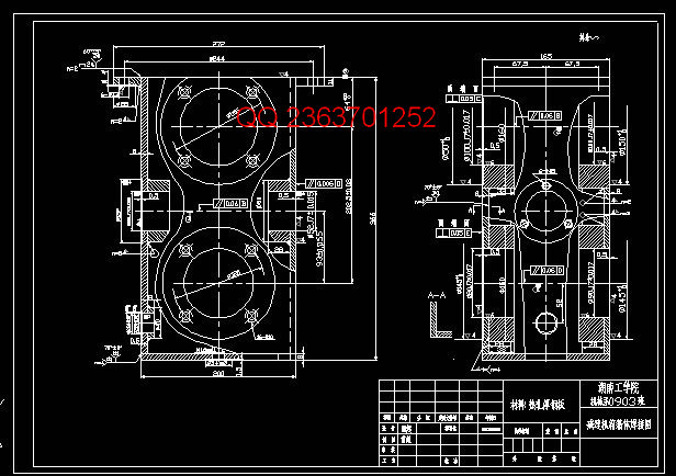
本次设计,主要是针对车辆用金属管材进行加工的切割机,完成的工作主要是切管机中的滚子,机体和减速箱部分的设计.包括传动装置的设计和计算,其中有电动机的选择,传动方案的拟定,各轴的转速,功率和转矩的计算.总体结构的设计,其中有各轴尺寸的设计,各主要传动件的结构尺寸的设计.并且针对以上的设计计算进行了详细的校核.最后通过得到的数据,绘制了总体装配图,减速机和滚子部分的装配图.然后又针对各主要基本件,绘制了多张零件图。为了确定最佳方案,采取了多种方案进行了认真分析、研究和比较。
关键词: 切管机;设计计算;结构设计;批量下料;方案
ABSTRACT
Rolling type pipe cutters design, is a technical innovation projects. Pipe cutters is mainly used for vehicles, industrial or building materials production batch of material work, suitable for cutting metal pipe. Its characteristic is, smooth, continuous, high efficiency, low labor strength, ensuring the dimension accuracy requirement, adapted to various environment in the work continuously
Rolling type pipe cutters work by motor with principle is: by v-belts transmission, worm gear reducer, gear to open a roller, thus promote (tube) rotation, realize the main movement during cutting. Meanwhile, manipulate the handwheel, through screw transmission, will move down the disc blade feeding, and increasing the pressure on the pipe blades, realize the pipe in the process of cutting jobs.
Raw data: roller speed for = 70 R.P.M., motor model selection JO2-22-4, its rated
power for = 1.5 kw, carrying speed = 1410 R.P.M., cut tube diameter D for 3/8 "~ 4"
This design is mainly for vehicles with metal pipes carry on the processing of cutting machine, completed work, mainly is the pipe cutters, the body and the roller gear box part of the design. Includes transmission device, the design and calculating, including motor driving scheme worked, the choice of the shaft, speed, torque and power calculation. Overall structure design, including the design of each shaft dimension, the main transmission parts. And the design of structure size for above a detailed design calculation of dynamicrigidity. Finally, through the data from the general assembly, mapped the speed reducer and roller part, the assembly drawing. Then in each major basic pieces, painted a detail drawings. In order to determine the optimal scheme took various schemes, carried on the earnest analysis, research and comparison.
Key words:Pipe cutters; Design calculation; Structure design; Batch next makings; scheme
目 录
1 方案的选择与论证................................................... 4
1.1 电动机的选择......................................................5
1.2 拟定传动方案......................................................6
1.3 总体结构设计.....................................................10
2 传动装置的设计与计算...................................................11
2.1 传动比分配.......................................................11
2.2 计算各轴的转速,功率和转矩.......................................11
2.2.1 各轴的转速................................................ 11
2.2.2 各轴的功率.............................................. 12
2.2.3 各轴传递的转矩...............................................12
3 进行传动机构的设计与计算................................................14
3.1 带传动设计........................................................14
3.2 齿轮传动设计......................................................15
4 结构设计.......................................................... 18
4.1 初算各轴的最小直径............................................... 18
4.2 计算各主要传动件的结构尺寸........................................19
4.3 初定轴承跨距......................................................22
5 设计总结................................................................27
参考文献..................................................................28
致 谢..................................................................29
附 录..................................................................30
实习报告..............................................................30
实习日记........................................................... ..33
|


