|
设计简介 |
设计描述:
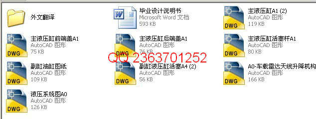
文档包括:
Word版设计说明书1份,共46页,约22000字
外文翻译一份
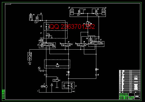
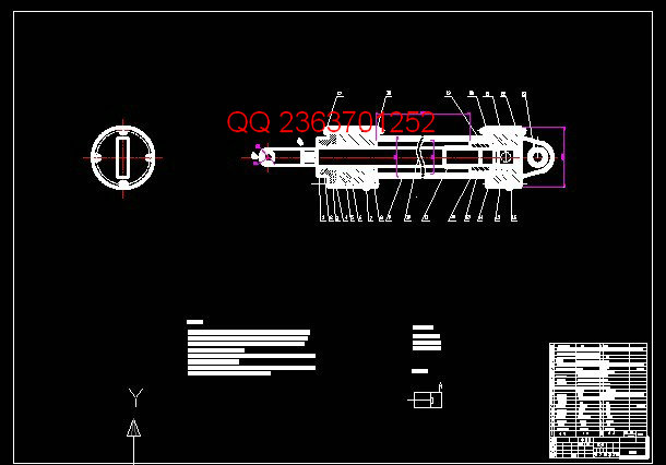
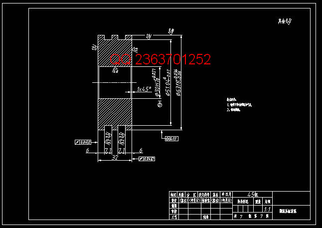
CAD版本图纸,共8张
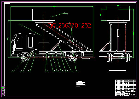
车载雷达液压升级系统设计
摘要
随着国际形势的动荡,局部战争的不断爆发,现代武器装备的不断更新,现代战争已进入了电子战,信息战时代,传统的机动型雷达已经不能满足现代战争的需要。各国为了提高自己的防卫,跟踪,识别和反击能力,高机动地面雷达应运而生。
天线快速,可靠地机动架设和撤收是车载雷达的基本要求之一。按传动系统的不同,雷达天线升降机构可分为机电式和液压式。与机电式相比,在输出同样功率的条件下,液压式的体积和质量小,承载能力大,可以完成较大重量雷达天线的架设,还可大大简化机械结构,减少机械零部件的数目,也便于实现自动控制。随着科技的发展,液压式传动系统已逐渐在雷达天线升降机构中被采用。本设计采用一种翻转式液压举升机构及其液压系统,可实现对较大型天线的高架,并且在天线的举升过程中,天线的姿态不变,架撤收过程平稳,可靠,快速
关键词:液压升降系统;汽车;雷达;
The design of car radar hydraulic upgrade system
Abtract
Turmoil as the international situation, local wars breaking out, constantly updated, modern weapons and equipment of modern warfare has entered the electronic warfare, information warfare era, the traditional mobile radar can not meet the needs of modern warfare. Countries in order to improve their defense, tracking, identification, and fight back ability, high-motorized ground radar came into being.
Fast, reliable motorized antenna erection and dismantling is one of the basic requirements of the automotive radar. For differences in the transmission system, the radar antenna lifting mechanism can be divided into electro-mechanical and hydraulic. With electromechanical compared to the same output power conditions, the hydraulic volume and mass of small carrying capacity, the larger weight of the radar antenna can be completed erection, but also greatly simplifies the mechanical structure, reducing the number of mechanical parts, also easy to achieve automatic control. With the development of science and technology, the hydraulic drive system has been gradually the radar antenna lifting mechanism is used. This design uses a flip-hydraulic lifting mechanism and its hydraulic system, can be elevated to the larger antenna, and in the process of lifting of the antenna, the antenna of the same attitude, erecting the closing process is smooth, reliable, fast
Keywords: hydraulic lift system; cars; radar;
目 录
1 绪论 1
1.1 课题研究背景 1
1.2 雷达车的特点 1
1.3 国内外机动雷达现状分析 2
1.4 设计的目的及任务 3
2 举升系统总体方案设计 5
2.1天线升降装置对液压系统的要求 5
2.2总体技术方案 5
2.3系统主要技术参数的确定 7
2.4举升机构液压系统及工作原理的设计 9
2.5设计特点分析 11
3 举升机构的液压系统设计计算 12
3.1 主液压缸的设计 12
3.1.1 液压缸缸体厚度计算 13
3.2.2 液压缸长度确定 13
3.2.3 缸体的材料 14
3.3.4 活塞杆直径的设计 14
3.3.5 活塞杆的材料 15
3.2 副液压缸的设计 17
3.2.1 液压缸缸体厚度计算 17
3.3 活塞的设计 18
3.3.1 活塞的材料 18
3.4 导向套的设计与计算 19
3.4.1 最小导向确定长度H的 19
3.4.2 导向套的结构 20
3.4.3 导向套的材料 20
3.5 端盖和缸低的设计与计算` 20
3.5.1 缸盖的材料 21
3.6 缸体的长度确定 22
3.7 缓冲装置的设计 22
3.8 密封件的选用 22
3.9 动密封部位密封圈的选用 23
3.10 液压缸的安装连接结构 23
3.11 液压缸油口的设计 25
4 液压泵的参数计算 26
4.1 泵的工作环境 26
4.2 主液压缸液压泵流量的确定 27
4.3 副缸液压泵流量的确定 27
4.4 主缸电动机功率的确定 28
4.5 副缸电动机功率的确定 28
4.7 油箱容积的确定 29
4.8 油管的选择 30
4.9 液压系统热性能验算 30
5 液压系统的安装 32
5.1 安装的基本要求: 32
5.1.1 系统安装前注意事项 32
5.1.2 系统安装时的注意事项 32
5.1.3 系统安装方法 34
5.2液压系统的调试 35
5.2.1 调试的目的 35
5.2.2 调试的步骤 35
5.2.3 调试的主要内容 36
结论 38
参考文献 39
致谢 40
毕业设计(论文)知识产权声明 41
毕业设计(论文)独创性声明 42
|


