|
设计描述:
文档包括:
Word版设计说明书1份,共55页,约17000字
CAD版本图纸,共5张
目录
摘 要 IV
Abstract V
第1章 前 言 1
1.1 驱动桥的发展现状 1
1.1.1 驱动桥的结构组成和功用 1
1.1.2 驱动桥的国内外情况及发展趋势 1
1.1.3 设计驱动桥时应当满足的要求 2
1.1.4 设计要求 3
第2章 驱动桥结构方案拟定 4
2.1 驱动桥内部各部件的功用 4
2.1.1 主减速器的类型和功用 4
2.1.2 差速器的类型和功用 4
2.1.3 轮边减速器的功用 4
2.2 确定驱动桥设计方案 5
第3章 主减速器设计 6
3.1主减速器的特点 6
3.1.1主减速器的齿轮类型 6
3.1.2 主减速器主,从动锥齿轮的支承形式 6
3.2 主减速器的基本参数选择与设计计算 7
3.2.1主减速器计算载荷的确定 7
3.2.2主减速器基本参数的选择 8
3.2.3 主减速器圆弧锥齿轮的几何尺寸计算 11
3.2.4 主减速器圆弧锥齿轮的强度计算 13
3.3主减速器轴承的载荷计算 15
3.3.1锥齿轮齿面上的作用力 15
3.3.2.主减速器锥齿轮轴承载荷的计算 17
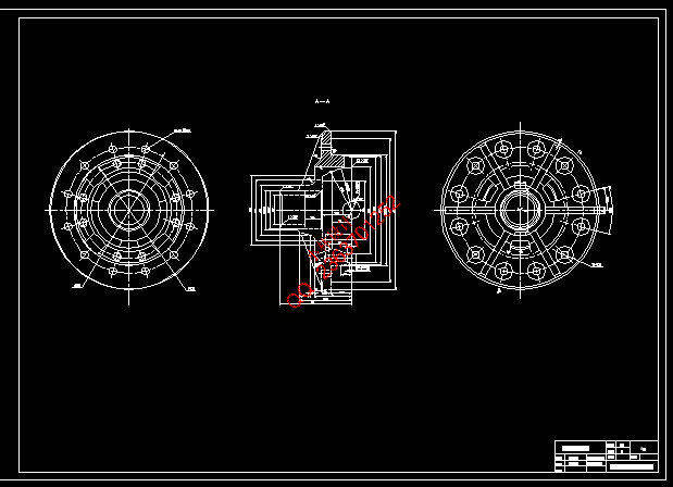
第4章 差速器设计 20
4.1 对称式圆锥行星齿轮差速器的结构 20
4.2 对称式圆锥行星齿轮差速器的设计 21
4.2.1 差速器齿轮的基本参数的选择 21
4.2.2 差速器齿轮的几何计算 24
4.2.3差速器齿轮的强度计算 25
第5章 驱动半轴的设计 27
5.1 全浮式半轴计算载荷的确定 27
5.1.1半轴的计算扭矩 27
5.1.2全浮式半轴直径的选择 28
5.1.3全浮式半轴的强度计算 28
5.1.4半轴花键的选择及强度校核 28
5.1.5半轴的结构设计及材料与热处理 30
第6章 轮边减速器 31
6.1 轮边减速器齿轮的设计 31
6.1.1齿轮参数的计算 31
6.1.2齿轮的校核 32
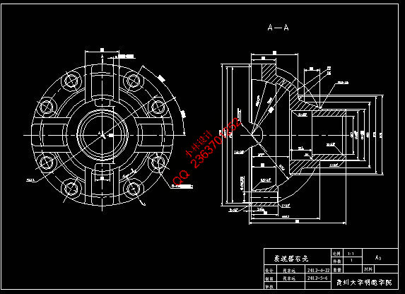
第7章 驱动桥壳设计 34
7.1整体式桥壳 34
7.1.1整体式桥壳分类 34
7.1.2驱动桥壳强度计算 35
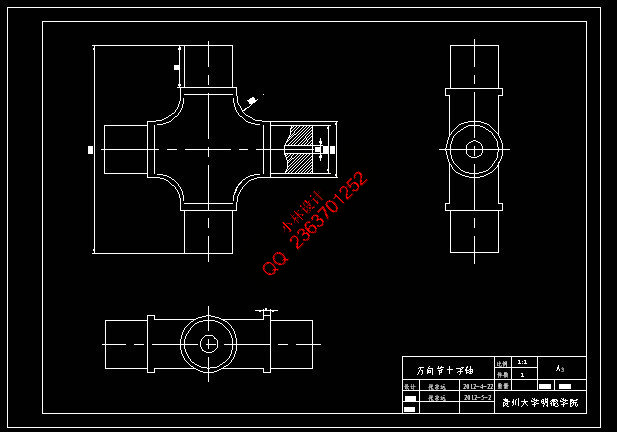
第8章 万向节的设计 38
8.1 万向节分类 38
8.1.1十字轴万向节 38
8.1.2、准等速万向节 38
8.1.3 等速万向节 39
8.1.4挠性万向节 40
8.2十字轴万向节设计 40
8.2.1 十字轴的设计 40
8.3万向传动的计算载荷及强度校核 43
8.3.1万向传动的计算载荷 43
8.3.2 十字轴万向节强度校核 43
8.3.2 十字万向节的轴承设计 44
第9章 结论 47
9.1 完成的内容与成果 47
9.2 该题目设计的意义 47
参考文献 48
致谢 49
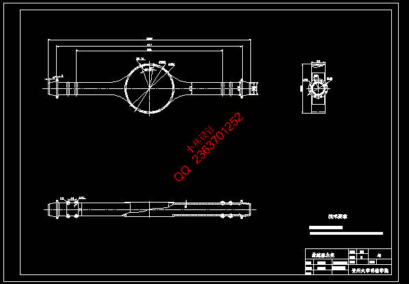
轮式挖掘机的万向节传动及驱动桥的设计
摘 要
本设计是做轮式挖掘机的万向节传动及驱动桥的设计,它处于传动系统的末端,传递较大的转矩,其工作的好坏直接影响到整机的工作性能。
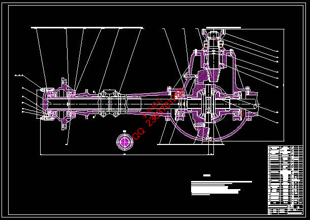
驱动桥的功用是通过主传动来改变转矩旋转轴线的方向,把纵置发动机的转矩传递到横置驱动桥两边的驱动轮上。通过主传动的锥齿轮改变传力方向,通过最终传动和主传动将变速箱输出轴的转速降低,增大转矩;通过差速器解决左右差速问题,减小转向阻力和轮胎磨损,从而协助转向。此外驱动桥壳还起传力和承重作用。
此次设计主要是对轮式挖掘机的整个驱动桥内部零部件进行设计计算,包括主减速器部分、差速器、轮边减速器部分以及万向节的选择,由于驱动桥部件的设计技术已有很好的发展,所以这次设计主要借鉴的是詹阳动力JYL608型挖掘机的一些参数展开的。此次设计的意义在于熟悉了机械设计的流程和对大学四年所学知识有一个整体的了解。
关键词:驱动桥,主减速器,差速器,轮边减速,万向节
The design of the universal joint transmission and drive axle of the wheeled excavator
Abstract
The design is the design of the universal joint transmission and drive axle wheel excavator, it is the end of the transmission system, passing a large torque, its work will have a direct impact on the work performance of the machine.
The function of the drive axle of the main drive to change the torque in the direction of the rotation axis, a longitudinal engine torque to the transverse drive axle on both sides of the driving wheel. Change the direction of the force transmission through the main drive bevel gear final drive and the main transmission gearbox output shaft speed is reduced, increasing the torque; solve the differential left and right through the differential to reduce steering resistance and tire wear, which to assist steering. In addition, the drive axle housing also from the power transmission and load-bearing role.
The design of the main internal parts of the drive axle of the wheel excavators, design calculations, including the choice of part of the main gear box, differential, wheel reducer part and universal joints, drive axle parts design techniques already well developed, so this design is the main reference is the parameter expansion Zhan Yang the power JYL608 excavator. The significance of the design is familiar with an overall understanding of the mechanical design process and four years of college knowledge.
Keywords: drive axle, main reducer, differential, wheel speed, universal joint
|