|
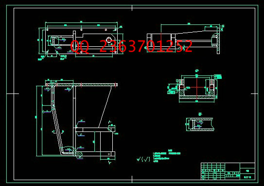
设计描述:
文档包括:
word版设计说明书一份,52页,约20000字
CAD版本图纸,共4张
摘 要
随着科技的进步,工业领域的自动化程度越来越高,作为机械行业,肩负着国家制造业的兴衰,也是衡量一个国家综合国力的主要标志。目前,在机械加工生产线上多数采用的是电、气、液相结合的一体化模式。板材送进装置是生产线上的重要环节,是连接主机和工作机的桥梁。本文讨论了汽车冲孔生产线上的送料装置的结构组成和工作原理,简单介绍了汽车冲孔生产线的发展状况、组成部分及其用途,并且在此基础上进行了改进,实现了板材的快速、准确定位。因此,成功设计该装置具有十分重要的意义,它可以在一定程度上促进生产自动化,减少运输时间,降低工人的劳动强度,提高生产效率,降低劳动成本,给企业带来更大的经济效益。
关键词:夹钳;上料装置;板材;冲孔
目 录
摘 要 I
Abstract II
第1章 绪论 1
1.1 汽车纵梁冲孔生产线上的上料装置研究的意义 1
1.2 汽车纵梁冲孔生产线的国内外发展情况 1
1.2.1 国外情况 1
1.2.2 国内情况 2
1.3 汽车纵梁冲孔生产线的工作原理 2
1.4 汽车纵深冲孔生产线的结构及用途 3
1.4.1 上料台车及吸盘上料机构 3
1.4.2 上料送进装置 3
1.4.3 主机部件 4
1.4.4 导料装置 5
1.4.5 下料工作台及接料架 5
第2章 送料装置设计方案 6
2.1 设计方案列举 6
2.1.1 设计方案一 6
2.1.2 设计方案二 7
2.1.3 设计方案三 7
2.2 设计方案比较 8
2.2.1 经济型分析 8
2.2.2 电机选择分析 8
2.2.3 传动方式比较分析 9
2.3 本装置设计方案 9
第3章 STPK120夹钳装置概述 10
3.1 STPK120夹钳装置简介 10
3.2 STPK120夹钳装置工作原理 10
3.3 传送装置总体结构及其各部分功能 11
3.4 传送料装置各部件结构 11
3.4.1 传感器 12
3.4.2 油缸 15
3.4.3 锁紧缸 15
3.4.4 支座 15
3.4.5 汽缸支架 15
第4章 板材力学分析 16
4.1 设计有关技术参数 16
4.2 板材力学分析 16
4.3 液压油的选择 18
4.3.1 液压油的选用原则 18
4.3.2 本装置液压油的选择 20
第5章 液压缸设计 22
5.1 缸筒的功能 22
5.2 油缸筒参数计算 22
5.2.1 液压缸的基本参数的确定 22
5.3 油缸工艺分析 24
5.3.1 工艺性分析 24
5.3.2 确定毛坯的制造形式 25
5.3.3 油缸的工艺过程制订 26
第6章 送料装置主要零件设计 28
6.1 减速机的选择 28
6.1.1 传动件选择 28
6.1.2 减速机的选择计算 28
6.2 伺服电机的选择 29
6.2.1 功率计算 29
6.2.2 电动机类型选择 30
6.3 齿轮的设计及校合 31
6.3.1 齿轮的选择 31
6.3.2 按齿面接触强度设计 31
6.3.3 按齿根弯曲强度设计 32
6.3.4 几何尺寸的计算 33
6.3.5 罗升齿轮的特点 34
6.4 齿条的设计及校合 34
6.4.1 罗升齿条的选用 35
6.4.2 齿条基本参数的确定 35
6.5 弹簧的设计 35
6.5.1 弹簧设计 35
6.5.2 弹簧的计算 36
6.5.3 弹簧设计参数确定与计算 37
6.6 齿轮平键校核 39
6.7 接近开关的设计 40
6.7.1 工作原理与分类 40
6.7.2 型号选择 40
6.7.3 接近开关作用 41
结 论 42
致 谢 43
参考文献 44
CONTENTS
Abstract I
Chapter 1 Introduction 1
1.1 Automobile Frame punching production line feeding device significance of the study 1
1.2 Car stringer punching production line at home and abroad 1
1.2.1 Abroad 1
1.2.2 The domestic situation 2
1.3 Automobile Frame punching production line works 2
1.4 Structure and use of the auto depth punching production line 3
1.4.1 The material trolley and suction feeding mechanism 3
1.4.2 The material sent to the device 3
1.4.3 Host Components 4
1.4.4 Conducting device 5
Chapter 2 feeders design 6
2.1 The design of enumeration 6
2.1.1 The first design 6
2.1.2 The second design 7
2.1.3 The third Design 7
2.2 The design comparison 8
2.2.1 The economic analysis 8
2.2.2 Motor Selection 8
2.2.3 Transmission 9
2.3 Device design 9
STPK120 clamp device Overview 10
3.1 STPK120 clamping devices Introduction 10
3.2 STPK120 clamp device works 10
3.3 Transfer unit in general stracture and fuction of each 11
3.4 The various components of the feed device structure 11
3.4.1 Sensor 12
3.4.2 The fuel tank 15
3.4.3 Locking cylinder 15
3.4.4 Supports 15
3.4.5 The cylinder bracket 15
Chapter 4, sheet metal mechanics 16
4.1 Design of the technical parameters 16
4.2 Analysis of sheet metal mechanics 16
4.3 Hydraulic oil of choice 18
4.3.1 The hydraulic oil selection principles 18
4.3.2 Hydraulic oil selection 20
Chapter 5, the hydraulic cylinder design 22
5.1 Cylinder functions 22
5.2 Cylinder tube parameter calculation 22
5.2.1 The basic parameters of the hydraulic cylinder to determine 22
5.3 Fuel tank process analysis 24
5.3.1 The analysis of the process 24
5.3.2 To determine the rough form of manufacturing 25
5.3.3 The fuel tank of the process to develop 26
Chapter 6, the main parts of the feeding device design 28
6.1 Reducer selection 28
6.1.1 The transmission choice 28
6.1.2 Reducer choice calculation 28
6.2 Servo motor selection 29
6.2.1 The power calculation 29
6.2.2 The motor type selection 30
6.3 gear design and the school together 31
6.3.1 Gear choice 31
6.3.2 Strength Design of tooth contact 31
6.3.3 Tooth root bending strength design 32
6.3.4 The calculation of the geometric dimensions 33
6.3.5 Law l gear features 34
6.4 Rack design and school closure 34
6.4.1 Luo l rack selection 35
6.4.2 Rack determine the basic parameters 35
6.5 Spring design 35
6.5.1 Spring design 35
6.5.2 Spring calculation 36
6.5.3 Spring design parameters and calculation 37
6.6 Gear level key check 39
6.7 The proximity switch design 40
6.7.1 Works and classification 40
6.7.2 Model selection 40
6.7.3 Proximity Switches role 41
Conclusions 42
Acknowledgements 43
References 44
| 


