|
设计简介 |
设计描述:
文档包括:
设计word版本说明书一份,共27页,约11000字
CAD版本图纸,共13张
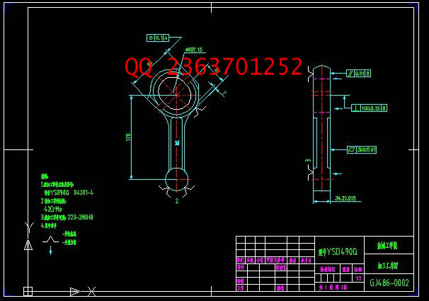
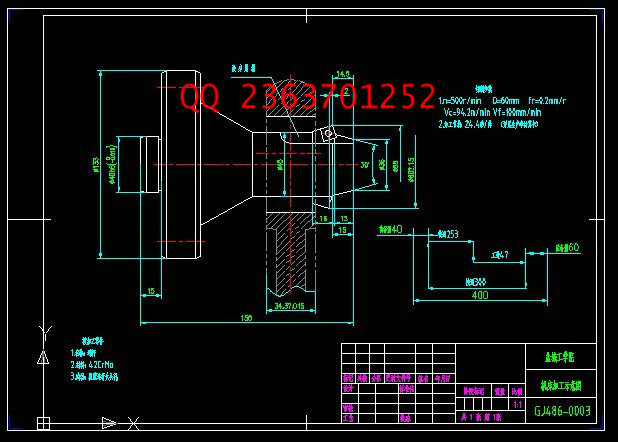
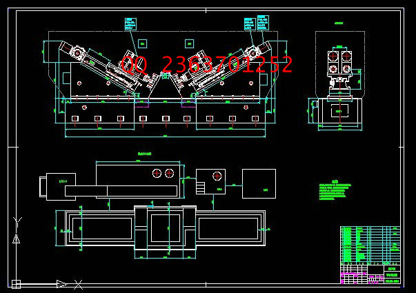
粗镗连杆大头孔专用镗床总体及镗削头设计
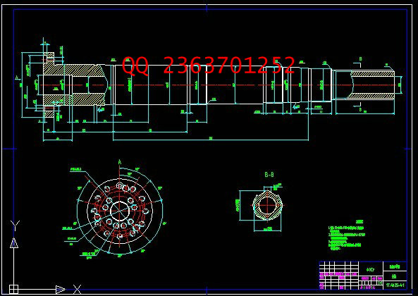
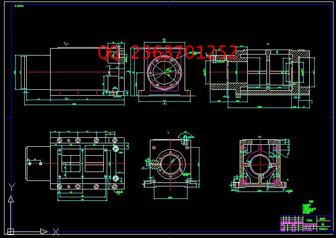
摘 要:本课题设计一台双面卧式专用镗床。该组合机床设计的内容主要包括总体设计和部件设计两部分。总体设计:本镗床用于粗镗加工连杆大头孔,一个工作循环可同时粗加工两个连杆的四个孔。根据工艺和加工的需要,两两并排设计4个专用的镗削头。为了使主轴轴承结构具有刚度好、精度高及调整简单的特点,选择了1TAb25的镗削头。但为了使1TAb25的镗削头能够在本专用镗床上使用,故将部分结构进行了改进设计。在专用镗床的设计中,完成了专用镗削头的总装配图和零件图的设计。为保证主轴的刚度与精度,在对主轴进行了校核计算。主轴中设计了两个锥度为1:12的的轴段用于安装支承和固定圆柱滚子轴承,由于镗削头的精度要求很高,在轴承处使用了锁紧螺母进行轴向固定。此外,还进行了主轴配套轴承的选用和校核。
此次设计的组合机床,结构简单、维护方便,尽量使用了通用零部件来降低制造成本,达到了设计的要求。
关键字:镗削头;组合机床;连杆;镗孔
Overall and boring design of machine tool for boring connecting bar
Abstract: This topic is to design a special double-sided horizontal boring lathe. The design of modular machine mainly includes overall design and part design. Overall design: this boring machine that I design is used to process big hole of Linkage, meanwhile, it also can process four hole of two linkage in a work cycle. According to the needs of technology and processing, we should design four special boring head which is two side by two side. Besides, I select 1TAb25 boring head in order to make the structure of spindle’s bearing having better stiffness, high precision, and simple adjustment as well. But in order to making 1TAb25boring head can be used in this special boring machine, I improved and designed some parts of it’s structure. During the design of special boring machine, I completed the design of overall assembly and parts assembly, moreover, I check and calculate spindle to guarantee stiffness and accuracy. I design two axis which taper is 1:12 to install bearing and fix bearing of cylindrical roller, I used locking nut to fix the direction of bearing owing to the reason of boring head’s high precision. In addition, I select and check matching bearing as well.
Modular Machine that I design not only have many advantages such as simple structure, easy maintenance. But also meet the design requirements , also I make full use of General parts to reduce the cost of manufacture in the same time.
Key words: Exclusive Boring; Modular Machine; Linkage; Boring hole
目 录
1 前 言 1
2 总体设计 3
2.1工艺方案的拟订 3
2.2 切削用量的确定 3
2.3计算切削力、切削扭矩及切削功率 4
2.3“三图一卡”的设计 6
2.3.1被加工零件工序图 6
2.3.2 加工示意图 8
2.3.3 机床联系尺寸图 9
2.3.4 机床生产率计算卡 9
3 专用镗削头设计 13
3.1镗刀的选用 13
3.2 轴的设计 13
3.2.1轴的结构工艺 13
3.2.2主轴的选用 14
3.2.3 主轴的强度校核计算 17
3.3主轴密封装置的选用 18
3.4 轴端连接方式 19
3.5 主轴支承轴承的选用 20
3.5.1主轴支承轴承选用 20
3.5.2 主轴轴承的寿命计算 21
4 设计小结 24
参 考 文 献 25
致 谢 26
附 录 27
|


