|
设计简介 |
文档包括:
WORD版本说明书一份,共73页,约46000字左右.
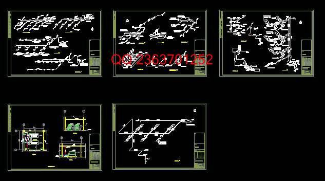
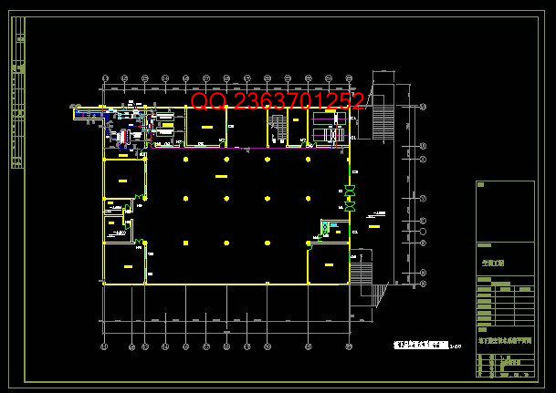
CAD版本图纸,共16张
北京市XX综合楼空调设计
摘 要:
北京市XX综合楼总建筑面积12956.3m2,空调面积为10074m2。本空调工程设计冷负荷采用谐波分析原理计算法,设计热负荷采用的方法是概算指标法;空调湿负荷的计算方法采用的是经验数据概算法;本工程根据各空调房间热湿负荷的特点及使用功能等工程实际,进行空调分区,分为七个中央空调区和多个局部空调区,同时根据各空调区的使用特点和负荷特点,合理地设置七个中央空调系统及多个局部空调系统,以有利于调节运行;本工程制冷机组采用制冷量大、效率高、噪声低的双压缩机-螺杆式水冷机组,并选用两台,其中一台兼做备用。
为消除空调房间内的余热和余湿,须对空气进行热湿处理,并经严格的热湿处理计算确定空调机组的冷热湿量和选用符合要求的空调机组。
本工程空调水系统庞大而复杂,且容易产生水力失调,所以选用了水力平衡性较好的同程式系统。同时要求配有比较完善的自控系统。
关键词:中央空调 局部空调 风机盘管 空调机组
ABSTRACT:
Bai-Si-Te synthetic building’s floor area of Beijing total 12956.3m2, the air conditioning area is 10074m2. In this air conditioning engineering, the computation of the designed cooling load used the overtone analysis principle and the designs method which the themal load used was the budgetary-estimating target law;The humidifying treatment load of an air conditioni- ng system computational method which used was the empirical data generally algorithm;Acc- ording to project reality for instance the heat-wet load characteristic and using function of va- rious air conditioned room and so on, carried on the air conditioning district for this project , and divided into seven central air conditioning areas and many partial air conditioning for be- nefitting adjustment and workingand simultaneously,according to the handling characteristics and the load characteristic of various air conditioning area, reasonably established seven cen- tral air-conditioning systems and many partial air-conditioning systems; This project refriger-ation unit uses double compressor-screw rod type water cooling unit of which the refrigerati- on quantity is high ,the efficiency is high, the noise is low, and concurrently selects two, one does spare.
In order to eliminate the over heat and the over wet in the air conditioned room, we must carry on heat-wet treatment to the air which is inputted, and after the strict heat-wet treatment computation,determinate air-conditioning unit's cold and hot and moisture content,and select the air conditioning units which conform to the request.
The aqueous system in this air conditioning project is huge and complex, and also is easy to have the water-power imbalance, therefore here has selected the same formula sys- tem which water power balanced state is better.Simultaneously it requests to have the quite pe- rfect automatic control system.
Key words: central air-conditioning,partial air-conditioning , fan-coil, air conditioning unit
目 录
第1章 设计说明…………………………………………………………………………… 1
1.1 工程概况……………………………………………………………………………… 1
1.2 设计依据……………………………………………………………………………… 1
1.3 空调室内外设计参数………………………………………………………………… 1
1.3.1 空调室内设计参数……………………………………………………………… 1
1.3.2 空调室外设计参数……………………………………………………………… 2
1.4 空调方案说明………………………………………………………………………… 3
第2章 空调负荷计算……………………………………………………………………… 4
2.1 空调系统设计冷负荷的计算………………………………………………………… 4
2.1.1地下商场空调冷负荷的计算 …………………………………………………… 4
2.1.2其他空调房间设计冷负荷的计算……………………………………………… 15
2.2 空调系统设计热负荷 ……………………………………………………………… 15
2.2.1空调室内设计热负荷的计算…………………………………………………… 16
2.2.2各空调系统的设计热负荷……………………………………………………… 16
2.3 空调设计湿负荷的计算 …………………………………………………………… 16
2.3.1各空调室内设计湿负荷的计算………………………………………………… 16
2.3.2各分区空调系统设计湿负荷的确定…………………………………………… 17
2.4 空调系统新风负荷的计算 ………………………………………………………… 17
2.4.1空调系统和空调室内新风量的确定…………………………………………… 17
2.4.2空调室内新风负荷和空调系统新风负荷的计算……………………………… 22
第3章 空气处理 ………………………………………………………………………… 22
3.1 空气处理方案 ……………………………………………………………………… 22
3.1.1全空气系统……………………………………………………………………… 22
3.1.2风机盘管加新风系统…………………………………………………………… 23
3.2 空气处理过程及计算 ……………………………………………………………… 24
3.2.1一至三区的空调系统空气处理过程与计算及其处理设备选型……………… 24
3.2.2四至七区的空调系统空气处理过程与计算及其处理设备选型……………… 30
3.3 局部空调机组选型 ………………………………………………………………… 35
第4章 气流组织 ………………………………………………………………………… 36
4.1 气流组织方案 ……………………………………………………………………… 36
4.1.1空调房间气流组织的形式……………………………………………………… 36
4.1.2空调房间送回风口的型式……………………………………………………… 37
4.1.3送回风口的布置方式…………………………………………………………… 38
4.2 气流组织计算 ……………………………………………………………………… 38
4.2.1地下商场气流组织计算和风口选型…………………………………………… 38
4.2.2一层休息间和大堂气流组织计算……………………………………………… 42
4.2.3一层餐厅气流组织计算及风口选择…………………………………………… 43
4.2.4四至七区空调房间气流组织和送风口的选型………………………………… 46
第5章 空调风系统设计 ………………………………………………………………… 47
5.1 空调风系统风管的选择 …………………………………………………………… 47
5.2 各空调风系统的布置 ……………………………………………………………… 47
5.3 各空调风系统的水力计算 ………………………………………………………… 48
5.3.1一区即地下商场空调风系统的水计算………………………………………… 48
5.1.2其他风系统水力计算…………………………………………………………… 50
第6章 空调水系统设计 ………………………………………………………………… 54
6.1 空调水管路系统的形式…………………………………………………………… 54
6.2 空调水管环路系统的划分 ………………………………………………………… 55
6.3 空调冷冻水-热水系统的管路计算………………………………………………… 56
6.3.1空调水系统的布置……………………………………………………………… 56
6.3.2空调水系统的设计流量………………………………………………………… 56
6.3.3各水系统的水力计算和水泵选择……………………………………………… 56
6.3.4系统的补水……………………………………………………………………… 59
6.4 空调冷却水系统管路计算 ………………………………………………………… 60
6.4.1冷却塔的选型…………………………………………………………………… 60
6.4.2冷却水循环系统管路计算……………………………………………………… 60
6.4.3冷却水循环系统补水量………………………………………………………… 62
6.5. 冷凝水管路设计…………………………………………………………………… 63
第7章 空调系统的冷热源 ……………………………………………………………… 64
7.1空调制冷机组的选择 ……………………………………………………………… 64
7.2分水器的选择 ……………………………………………………………………… 64
7.3热源设备-水/水换热器的选择…………………………………………………… 64
第8章 空调系统的消声与隔振 ………………………………………………………… 65
8.1空调系统的噪声控制 ……………………………………………………………… 65
8.2空调装置的隔振 …………………………………………………………………… 65
第9章 空调系统的监测与调节 ………………………………………………………… 66
结束语……………………………………………………………………………………… 67
附录………………………………………………………………………………………… 68
参考文献 ………………………………………………………………………………… 118
致谢 ……………………………………………………………………………………… 119
第1章 设计说明
1.1 工程概况
本工程为位于北京市(位于北纬39度,东经116度)昌平区的一栋综合楼,总建筑面积约12956.3㎡,建筑高度为13.5m,共5层,为一类建筑。地下室主要有商场、办公室和制冷机房,层高4.5米,总面积约1612.6㎡;第一层用于洗浴、休息、餐饮,另有小商店和大堂,层高4.5米,总面积3394㎡;第二层主要用于餐饮和休息,层高4.5米,2868.6㎡;第三层主要用于住宿和娱乐,层高4.5米,面积为2944.7㎡;第四层用于开会和住宿,另有舞厅,层高4.5米,总面积2136.4㎡。应业主要求,此次空调设计(初步设计)范围为1至4层的通风空调系统和地下室的空调设计。
|


