 |
 |
|


|
设计名称 |
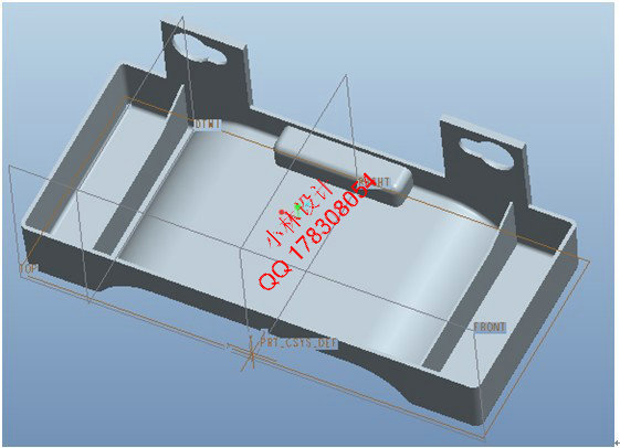
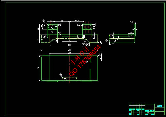
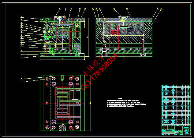
基于ProE的接水盒注塑模具设计[Proe三维] |
 |
|
设计编号 |
V101 | |
|
设计软件 |
AutoCAD, Word | |
|
包含内容 |
见右侧图片 | |
|
说明字数 |
18000字 | |
|
图纸数量 |
见右侧图片 | |
|
推荐指数 |
较高 | |
|
价格: |
价格优惠中 | |
|
整理日期 |
2013.9.26 | |
|
整理人 |
小林 | |
|
购买流程 |
<查看如何购买本站设计> |
|
设计简介 |
设计描述:
文档包括:
word说明书一份,共44页,约18000字
任务书一份
开题报告一份
外文翻译一份
CAD版本图纸,共10张
PROE三维图纸,一套
摘 要
注射成型是热塑性塑料成型的主要方法之一,可以一次成型形状复杂的精密塑件。本次设计中,主要运用到了
所学的注射模设计以及相关机械设计等方面的知识。分析了一副注射模的一般设计过程,即注射成型的分析、
注射机的选择及相关参数的校核、模具的结构设计、注射模具设计的有关计算、模具总体尺寸的确定与结构草
图的绘制、模具结构总装图和零件工作图的绘制等。设计主要包括成型位置及分型面的选择,模具型腔数的确
定及型腔的排列布置和流道布局,还有浇口位置的选择,模具工作零件的结构设计,抽芯机构的设计,浇注系
统的设计,推出机构的设计,斜导柱的设计等。设计过程主要利用了Pro/E进行三维零件的绘制并根据设计计算
绘制出模具的型芯和型腔以及基本模架等,然后用Auto CAD进行二维装配图和零件图的绘制,最后通过对整体
结构的校核,提高了其稳定性和可靠性。
关键词:接水盒;注塑模;ABS塑料
Abstract
Injection molding is one of the main methods for thermo plastics, and it can once-form delicate
plastic members with sophisticated shape. In this design, the knowledge of injection mold design
and related mechanical design are mainly used. The design process of a injection mold is
analyzed, that is, the analysis of injection molding, the selection of the injection molding
machine and the check of the related parameters of it, the structural design of the mold,, the
related calculation of the injection mold design, the determination of the overall size of the
mold and the drawing of the sketch, the drawing of the assembly diagram of the mold structure and
the parts diagram, and so on.. the design includes the choice of the molding location and the
parting surfaces, the determination of the number of the mold cavity, the layout arrangement and
the runner layout of the cavity, as well as the choice of the gate location, the structural
design of the mold parts、the core-pulling mechanism、the gating system、the ejection mechanism
and so on.Design process mainly uses the Pro/E 3D part drawing and according to the design
drawing of the mould core and cavity, and basic mold rack and so on, then use Auto CAD 2D
assembly drawing and parts drawing, at last, by check, for the whole structure to improve its
stability and reliability.
Keywords:water receiver;injection mold; ABS plastic
目 录
摘 要 III
ABSTRACT IV
目 录 V
1 绪论 1
1.1 塑料模具设计的研究内容和意义 1
1.2 塑料模具国内外发展现状 1
1.3 本课题应达到的要求 2
2 塑件分析 3
2.1 材料的选择 3
2.2 塑件的几何形式及结构分析 4
3 设备的选择与校核 6
3.1 塑件质量的计算 6
3.2 型腔数量的确定 6
3.3 注射机参数的校核 7
3.3.1 注射量校核 7
3.3.2 塑件在分型面上的投影面积与锁模力的校核 7
3.4 开模行程的校核 8
3.5 脱模力Q 8
4 浇注系统和排溢系统的设计 10
4.1 塑料制件在模具中的位置 10
4.2 浇注系统的设计 11
4.2.1 主流道的设计 11
4.2.2 主流道尺寸的确定 12
4.2.3 浇口位置的选择 12
5 成型零部件的设计与计算 13
5.1 成型零件的结构设计 13
5.1.1 型腔(或凹模)的设计 13
5.1.2 型芯(或凸模)的设计 13
5.2 成型零件工作尺寸的计算 14
5.2.1 型腔外形尺寸的确定 14
5.2.2 型芯外形尺寸的确定 15
5.2.3 型腔深度和型芯高度尺寸的计算 17
5.2.4 型腔侧壁厚度的计算 17
5.2.5 型腔底板厚度的计算 17
5.2.6 中心距尺寸的计算 18
6 脱模机构的设计 19
6.1 脱模力的计算 19
6.2 推出机构的设计 20
6.3 推出机构的复位与导向 22
6.4 模架的选取 22
7 侧向分型与抽芯机构 24
7.1 抽芯距的确定 24
7.2 抽芯机构设计 24
7.2.1 斜导柱抽芯的工作原理及设计原则 24
7.2.2 斜导柱倾斜角的选择 25
7.2.3 斜导柱直径计算 25
7.2.4 斜导柱长度计算 25
7.3 侧滑块的设计 25
7.3.1 侧滑块形状设计 25
7.3.2 侧滑块定位装置的设计 26
7.3.3 导滑槽的设计 26
7.3.4 楔紧块的设计 27
8 合模导向机构设计 28
8.1 导柱 28
8.2 导套 28
9 温度调节系统 30
9.1 冷却系统的设计原则 30
9.2 冷却回路的尺寸确定 30
9.2.1 冷却回路所需的总面积 30
9.2.2 冷却回路的总长度 31
10 结论与展望 32
10.1 结论 32
10.2 不足之处及未来展望 32
致 谢 33
参考文献 34
|
|
部分图纸 截图 |
    |
|
说明: |
如需了解本设计的具体详细信息请联系本站客服,说明看哪个设计(编号)哪个详细部分,我们将远程或截图给您观看. 机械毕业设计|论文 |

| [要求PR≥2,百度收录≥1000页;联系QQ:178308054] |
声明:根据《互联网传播权保护条例》本站,小林机械资料商城,所列资料均属原创者所有,仅供学习交流之用,请勿转载并做其他非法用途。
Powered by 小林机械资料商城 © 2013-2020 All Rights Reserved. 客服QQ:178308054
喜欢www.xiaolinbysj.com,请告诉你QQ上的5位好友,多谢您的支持!
Powered by 小林机械资料商城 © 2013-2020 All Rights Reserved. 客服QQ:178308054
喜欢www.xiaolinbysj.com,请告诉你QQ上的5位好友,多谢您的支持!