|
设计简介 |
设计描述:
文档包括:
WORD版设计说明书1份,共57页,约21000字
任务书一份
开题报告一份
PPT答辩一份
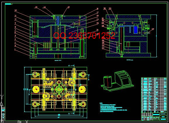
CAD版本图纸,共22张
中文摘要
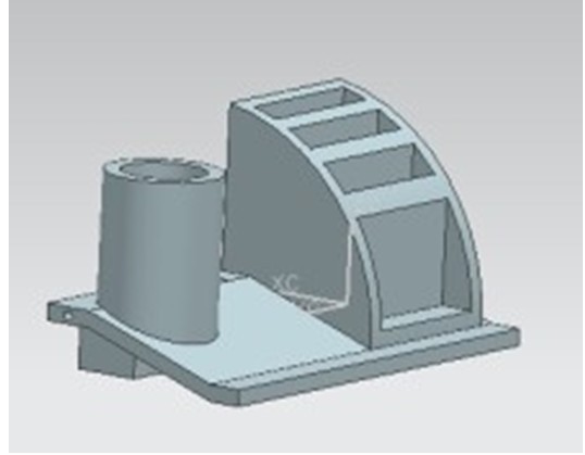
本文详细地阐述了多功能笔盒架注射模具的设计过程。设计了注射模具中的各个系统,如浇注系统、导向与定位机构、侧向分型与抽芯机构,并对塑料材料性能进行了分析,选择合适的注射机。根据塑件的产品数量要求,以及结构要求,该模具采用一模二腔。整个设计过程使用UG软件进行参数化设计,使整个模具设计过程简单明了。利用Mlodflow软件进行模流分析,为模具设计和成型工艺的确定提供参照依据。使用UG软件设计成型零件以及非标零件,从而进行全方面的参数化设计,即对模具进行分模、生成元件、装配、试模、开模、模架的选择等设计工作。同时应用UG软件可快捷地将三维图转化为二维工程图,直接指导生产。针对塑件的特点,本模具设计了侧抽芯滑块机构,也构成了本次模具设计的主要内容。
关键词 塑料模具 侧抽芯 注射模 注射机 模架
毕业设计说明书(论文)外文摘要
Title: Multifunctional pen rack box of injection mold design
Abstract
This paper expatiates a multi-function pen boxes frame injection mould design process. The design of injection mould includes pouring system, orientation and the position of the institutions, side parting and core-pulling mechanism. The plastic material properties are analyzed, and the injection machine is choosed appropriately. According to the number of plastic parts product requirements, and the structural requirements, the mould cavity with the two. The whole mould is designed by UG software, it makes the whole mold design process more simpler and clearer. Mlodflow software mold flow analysis can provides reference basis for the design and forming technology. Using UG software design molding parts and non-standard parts, and thus for all aspects of the parametric design, includes mold parting, and the formation of components, assembling, mode testing, mold opening, choice of formwork. At the same time using UG can easily transfer a 3d figure into a 2d engineering graphics, which can directly be used in producing. According to the characteristics of the plastic parts, the mould includes a side core-pulling slider mechanism, and this forms the main content of the design.
Keywords plastic mold injection mold injection side core pulling machine mold
目 录
前言 1
第一章 塑料模的功能 2
第二章 塑件成型工艺分析 3
2.1 拟定制品成型工艺 3
2.2 热塑性塑料聚丙烯的注射成型工艺 3
2.2.1 聚丙烯的注射成型工艺参数 3
2.2.2 聚丙烯材料综合性能分析 4
第三章 拟定模具结构形式 5
3.1 分型面位置的确定 5
3.2 确定型腔数量及排列方式 6
第四章 注塑机型号的确定 7
4.1 注射量的计算 7
4.2 塑件和流道凝料在分型面上的投影及所需锁模力的计算 7
4.3 选择注射机 8
4.4 有关参数的校核 10
第五章 浇注系统形式和浇口的设计 12
5.1 浇注系统的设计 12
5.1.1 主流道设计 14
5.1.2 分流道的设计 16
5.2 浇口的设计 18
5.2.1浇口设计的技术要求 18
5.2.2浇口尺寸的确定 20
5.3 冷料穴的设计 21
5.4 拉料杆的设计 22
5.5 浇注系统的平衡 22
5.5.1 分流道平衡 23
5.5.2 浇口平衡 23
第六章 模架的确定和标准件的选用 24
6.1 模具各个板料尺寸的确定 24
6.1.1 定模座板 24
6.1.2 定模板 25
6.1.3 动模板 25
6.1.4 动模垫板 25
6.1.5 垫块 25
6.1.6 动模座板 26
第七章 合模导向机构的设计 27
7.1 导向结构的总体设计 27
7.1.1 导柱的设计 27
7.1.2 导套的设计 28
第八章 脱模推出机构的设计 29
8.1 脱模推出机构的设计原则 29
8.2 制品推出的基本方式 29
8.3 塑件的推出机构 29
8.4 推杆推出机构的设计要点 30
8.5 复位机构设计 31
第九章 抽芯机构设计 32
9.1 侧向分型与抽芯机构的分类 32
9.2 斜导柱抽芯机构的设计 32
9.2.1 斜导柱的倾斜角的确定 33
9.2.2 侧向抽心力的计算 33
9.2.3 斜导柱的弯曲力的计算 33
9.2.4 斜导柱直径的计算 34
9.2.5 斜导柱的长度计算 34
9.2.6 锁紧楔的设计 35
第十章 成型零部件的设计 36
10.1 成型零件的结构设计 36
10.1.1 凹模的结构设计 36
10.1.2 凸模的结构设计 37
10.2 成型零件工作尺寸的计算 38
10.2.1 响工作尺寸的因素 38
10.2.2 成型零件工作尺寸的计算 39
10.3 成型零件强度计算 41
10.3.1 型腔侧壁厚度计算 41
第十一章 排气系统的设计 43
11.1 排气设计的要点 43
11.2 排气系统的几种方式 43
第十二章 温度调节系统设计 45
12.1 加热系统设计 45
12.2 冷却系统设计 45
12.2.1冷却系统的设计原则 45
12.2.2 冷却回路的布置: 46
12.3 型芯的冷却 47
12.4 冷却系统的有关计算: 47
结束语 49
致 谢 50
参考文献 51
|


