|
设计简介 |
设计描述:
文档包括:
Word版说明书一份,41页,约18000字
翻译一份
CAD版本图纸,共8张
毕业设计(论文)任务书
专业 机械设计制造及其自动化 班级 XXX 姓名 XXX 下发日期 2011-03-05
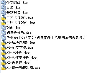
题目 阀体工艺规则设计及铣夹具设计
专题 1. 设计阀体零件加工工艺设计
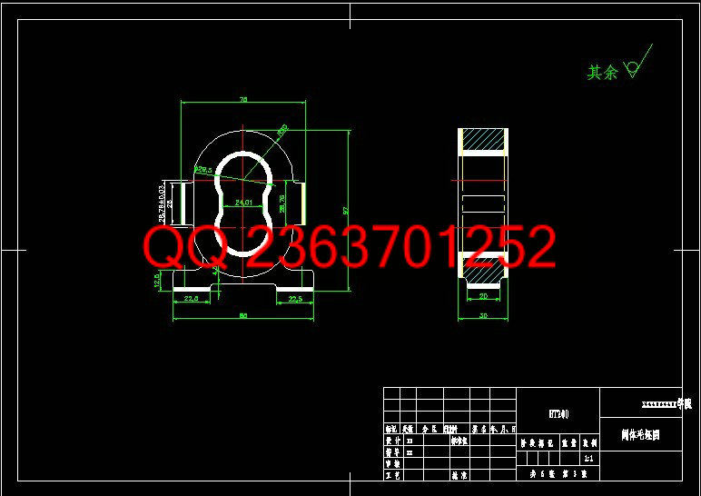
2. 铣平面夹具设计
主要 内 容 及 要
求 要求: 在教师的指导下,独立完成设计任务,培养较强的创新意识和学习能力,获得机械工程师的基本训练。使整个设计在技术上是先进的,在经济上是合理的,在生产上是可行的。工艺规程设计应该满足加工质量,生产率,经济性要求,机床夹具设计方案应该合理,有一定的特色和见解。计算步骤清晰,计算结果正确;设计制图符合国家标准;使用计算机设计,计算和绘图;说明书要求文字通顺,语言简练,图示清晰。
必须以负责的态度对待自己所做的技术决定,数据和计算结果。
主要内容:
(1) 确定生产类型,对零件进行工艺分析。
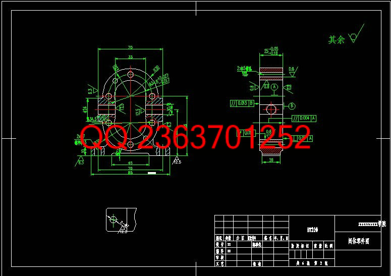
(2) 选择毛胚种类及其制造方法,绘制毛坯综合图。
(3) 拟定零件的加工工艺过程,选择各工序的加工设备和工艺装备,确定各工序切削用量和工学尺寸,计算某一代表工序的工时定额。
(4) 填写工艺文件: 工艺过程卡片(或工艺卡片),工序卡片(可视工作量大小只填部分主要工序的工序卡片)。
(5) 设计指定工序的专用夹具,绘制装配总图和主要零件图。
(6) 撰写毕业设计说明书。
成果形式: 设计说明书不少于10000万字,查阅文献10篇以上,绘制图纸折合总量不少于2张A0
主要技术参数 该零件图一张,年生产纲领5000件,每日一班。
进 度 及 完 成 日 期 3月23日—4.月3日 :实习 二周
4月6日—4月10日 :绘制被加工零件图和毛胚图 一周
4月13日—4月24日 :制定加工路线,编制工艺卡 二周
4月27日—5月8日 :进行设计和计算 二周
5.月11日—5月22日 :设计一套夹具装配图 二周
5月25日—5月29日 :设计夹具的零件图 一周
6月1日—6月56日 :外文资料翻译 一周
6月.8日—6月12日 :编制和整理设计计算说明书 一周
6月15日—6月19日 :机动 一周
6月22日—6月26日 :准备答辩和答辩
摘 要
本次设计内容涉及了机械制造工艺及机床夹具设计、金属切削机床、公差配合与测量等多方面的知识。
阀体加工工艺规程及其钻孔的夹具设计是包括零件加工的工艺设计、工序设计以及专用夹具的设计三部分。在工艺设计中要首先对零件进行分析,了解零件的工艺再设计出毛坯的结构,并选择好零件的加工基准,设计出零件的工艺路线;接着对零件各个工步的工序进行尺寸计算,关键是决定出各个工序的工艺装备及切削用量;然后进行专用夹具的设计,选择设计出夹具的各个组成部件,如定位元件、夹紧元件、引导元件、夹具体与机床的连接部件以及其它部件;计算出夹具定位时产生的定位误差,分析夹具结构的合理性与不足之处,并在以后设计中注意改进。
关键词:工艺、工序、切削用量、夹紧、定位、误差。
Abstract
This design content has involved the machine manufacture craft and the engine bed jig design, the metal-cutting machine tool, the common difference coordination and the survey and so on the various knowledge.
Body process planning and drilling fixture was designed to include part machining process design, process design, and dedicated fixture design of three parts. In process design, analysis of the part must first understand the parts of the process re-engineering the structure of a blank, and select a good part of the processing of the base to design parts process route; followed by the various working steps on the part of the procedures for the size of the calculation, the key is to determine the various stages of work out of process equipment and cutting consumption; then dedicated fixture design, selection of design out of all the component parts fixture, such as the positioning components, clamping components, guiding elements, the specific folder connection with the machine parts and other components; calculate the positioning fixture positioning error generated, analysis fixture structure is reasonable and deficiencies, and attention to improving the design in the future.
Keywords: The craft, the working procedure, the cutting specifications, clamp, the localization, the error
|