 |
|


|
设计名称 |
横拉杆接头加工工艺规程及加工螺纹孔夹具设计[毕设] |
 |
|
设计编号 |
V291 | |
|
设计软件 |
AutoCAD, Word | |
|
包含内容 |
见右侧图片 | |
|
说明字数 |
13000字 | |
|
图纸数量 |
见右侧图片 | |
|
推荐指数 |
较高 | |
|
价格: |
价格优惠中 | |
|
整理日期 |
2013.09.26 | |
|
整理人 |
小林 | |
|
购买流程 |
<查看如何购买本站设计> |
|
设计简介 |
设计描述: 文档包括:
Word版设计说明书1份,共40页,约13000字 摘 要
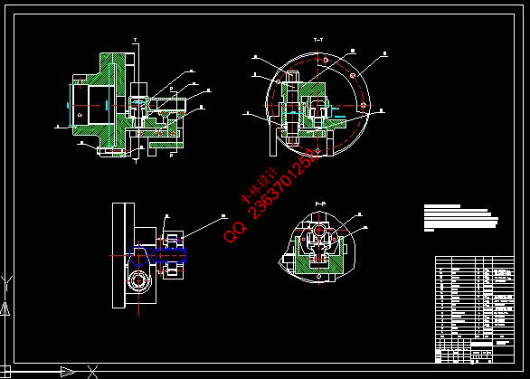
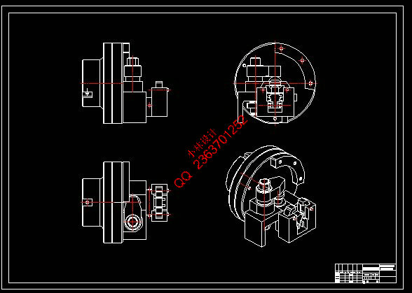
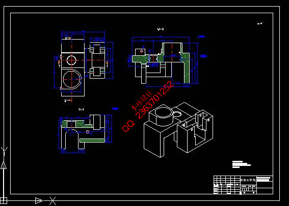
接头零件主要加工表面是平面及孔。由加工工艺原则可知,保证平面的加工精度要比保证孔的加工精度容易 。所以本设计遵循先面后孔的原则。并将孔与平面的加工明确划分成粗加工和精加工阶段以保证加工精度。 基准选择以右接头M52螺纹孔作为精基准,以不加工外圆作为精基准作为精基准。主要加工工序安排是先以镗 削M52螺纹孔做为其他面的定位基准,再以端面定位加工出工艺孔。在后续工序中除个别工序外均用端面和工 艺孔定位加工其他孔与平面。整个加工过程均选用普通车床。 关键词 :汽车转向横拉杆右接头 加工工艺 专用夹具 ABSTRACT
procedures and some process of special jig design. The car turned to horizontal bars right joint parts processing surface is flat and main hole. The processing technology, it is known that guarantee the principle in the plane of the machining accuracy than guarantee hole machining accuracy easy. So this design follow the principle of face first hole. And in the plane of the hole processing clear divided into rough machining and intensive processing stage in order to ensure that the processing accuracy. Benchmark choose the right joint M52 threaded hole as pure benchmark, with the benchmark as fine processing round as fine a benchmark. Main processing process arrangement is first to boring cut M52 threaded hole as the other position datum, again with end face positioning processing technology hole out. In the subsequent process in addition to the individual with the process are face and technology hole hole and
other plane positioning processing. The whole process are chosen for ordinary lathe.
目录
图二所以)。 3 |
|
部分图纸 截图 |
    |
|
说明: |
如需了解本设计的具体详细信息请联系本站客服,说明看哪个设计(编号)哪个详细部分,我们将远程或截图给您观看. 机械毕业设计|论文 |

| [要求PR≥2,百度收录≥1000页;联系QQ:178308054] |
Powered by 小林机械资料商城 © 2013-2020 All Rights Reserved. 客服QQ:178308054
喜欢www.xiaolinbysj.com,请告诉你QQ上的5位好友,多谢您的支持! 皖ICP备2021006205号-1
