 |
|


|
设计名称 |
柴油机齿轮室盖钻镗专机总体及夹具设计 |
 |
|
设计编号 |
n015 | |
|
设计软件 |
AutoCAD, Word | |
|
包含内容 |
见右侧图片 | |
|
说明字数 |
11000字 | |
|
图纸数量 |
见右侧图片 | |
|
推荐指数 |
较高 | |
|
价格: |
价格优惠中 | |
|
整理日期 |
9.26 | |
|
整理人 |
小林 | |
|
购买流程 |
<查看如何购买本站设计> |
|
设计简介 |
设计描述:
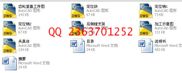
文档包括:
设计word版本说明书一份,共26页,约11000字
CAD版本图纸,共7张
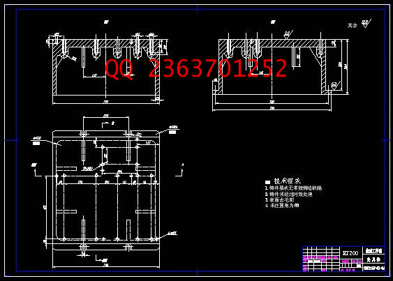
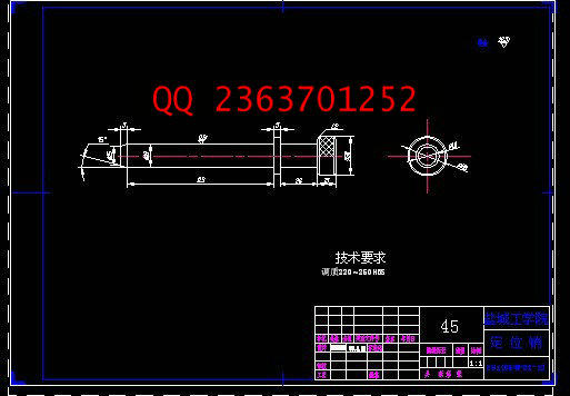
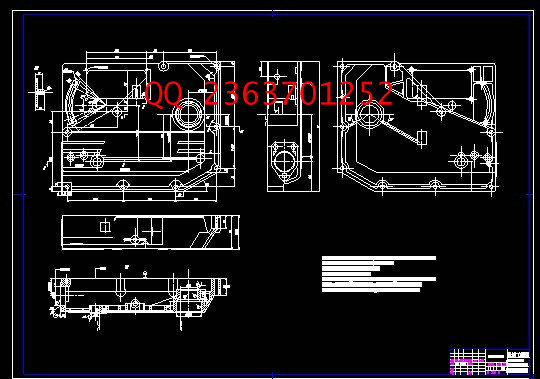
柴油机齿轮室盖钻镗专机总体及夹具设计
摘要:为保证ZH1105W柴油机齿轮室盖孔加工及保证相应的位置精度,设计一台钻镗组合机床。在完成“三图一卡”的基础上,完成夹具设计。
根据ZH1105W柴油机齿轮室盖的工序图分析其精度、表面粗糙度、技术要求、加工部位尺寸、形状结构、材料硬度、工件刚性及零件的批量的大小不同,确定被加工零件工艺方法和工艺过程,确定该组合机床的总体设计方案;考虑该零件表面结构的不规则性但有较高精度的孔需要加工,定位基准选择“一面双孔”是最佳的方法。选择通用导套,保证零件上孔的位置精度。选用液压滑台来保证所需要的进给力。动力箱和机床底座都是经过严格的计算后再选择合适的标准件,减少机床设计周期和成本;在夹具设计方面采用“一面两销”的定位方案保证被加工孔的准确定位和尺寸精度。考虑到需要的夹紧力比较大和手动夹紧的局限性,选用了液压自动夹紧的方案,提供稳定的夹紧力,减少工人的操作时间并且满足中批量生产的要求。
此次设计的组合机床,结构简单、维护方便,大量使用了通用部件来降低制造成本,达到了设计的要求。
关键词:齿轮室盖;组合机床; 总体设计; 夹具;
Overall and jig design of drilling and boring modular machine for the diesel engine gear cap
Abstract: In order to guarantee the hole processing and the corresponding position precision of the ZH1105W diesel engine gear cap, to drilling and the boring modular machine is designed. It mainly completes the jig design bases on “three charts and a card”.
According to the working procedure chart of the ZH1105W diesel engine’s gear cap analysis work piece’s precision, the surface roughness, the specification, the processing spot size, the shape structure, material degree of hardness, the work piece rigidity and the different of the components batch size to definite technique and technological process, determine aggregate machine-tool’s overall plan. Consider to the irregularity components but have high accuracy holes to be processing. So, “two holes at a face” is the best localization plan. Choiceing the general leads the wrap to Guarantee the hole of the components’ position precision. In order to guarantee the needs of the entering strength, we select hydraulic pressure sliding table. The power box and the engine bed are the standard parts base on our strict computation, so that we can greatly reduce the engine bed design cycle and the cost; In the jig aspect, we use the "two sells at the same face" for the localization plan. Only this way, we can guarantee the hole the accurate localization and the size precision. Considered to the strength of the manual clamps quite be small, selecting the hydraulic pressure clamps is the best way. It could provide stably clamps the strength, reduced worker's operating time and to satisfy the volume production request greatly.
Besides satisfying the processing request, the structure is simple, the maintenance is convenient. The general parts are massively used to reduce the production cost and meet the design requirements.
Key words: The gear cap; Modular machine-tool; Overall design; Jig;
目 录
1前言………………………………………………………………………………………1
2组合机床总体设计………………………………………………………………………2
2.1组合机床工艺方案的制定…………………………………………………………….2
2.2定位基准的选择……………………………………………………………………….2
2.3确定机床布置型式及结构方案……………………………………………………….3
2.4本工序的加工方法…………………………………………………………………….3
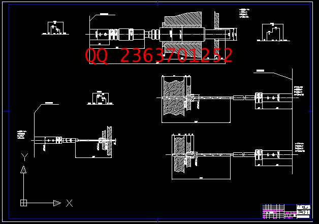
2.4.1刀具的选择…………………………………………………………………………..3
2.4.2右侧面钻9-¢9……………………………………………………………………..3
2.4.3左侧面钻6-¢5………………………………………………………………………7
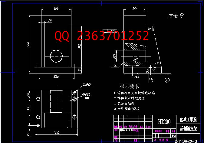
2.4.4后侧镗¢45H8………………………………………………………………………11
2.4.5机床生产率计算卡………………………………………………………………….13
3夹具设计…………………………………………………………………………………15
3.1定位原理及其实现……………………………………………………………………15
3.2误差分析………………………………………………………………………………15
3.2.1影响加工精度的因素……………………………………………………………….16
3.2.2保证加工精度……………………………………………………………………….17
3.3夹紧方式………………………………………………………………………………18
3.4夹紧力数值的计算……………………………………………………………………18
3.4.1确定夹紧力时应考虑的计算系数…………………………………………………18
3.4.2确定夹紧力………………………………………………………………………….19
3.5夹紧点数目及位置…………………………………………………………………..19
3.5.1夹紧点的数目………………………………………………………………………19
3.5.2夹紧点的位置………………………………………………………………………20
3.6夹具的主要零件结构设计…………………………………………………………..21
3.6.1钻模类型选择………………………………………………………………………21
3.6.2钻套的结构设计……………………………………………………………………21
3.6.3钻模板的结构设计…………………………………………………………………21
4零部件的设计绘制…………………………………………………………………….23
4.1绘制尺寸联系图…………………………………………………………………….23
4.2绘制加工零件工序图……………………………………………………………….23
4.3绘制加工示意……………………………………………………………………….23
4.4绘制夹具装配图及其零件图……………………………………………………….23
5结论………………………………………………………………………………….24
参考文献………………………………………………………………………………25
致谢……………………………………………………………………………………26
附录……………………………………………………………………………………27
|
|
部分图纸 截图 |
     |
|
说明: |
如需了解本设计的具体详细信息请联系本站客服,说明看哪个设计(编号)哪个详细部分,我们将远程或截图给您观看. 机械毕业设计|论文 |

| [要求PR≥2,百度收录≥1000页;联系QQ:178308054] |
声明:根据《互联网传播权保护条例》本站,小林机械资料商城,所列资料均属原创者所有,仅供学习交流之用,请勿转载并做其他非法用途。
Powered by 小林机械资料商城 © 2013-2020 All Rights Reserved. 客服QQ:178308054
喜欢www.xiaolinbysj.com,请告诉你QQ上的5位好友,多谢您的支持! 皖ICP备2021006205号-1
Powered by 小林机械资料商城 © 2013-2020 All Rights Reserved. 客服QQ:178308054
喜欢www.xiaolinbysj.com,请告诉你QQ上的5位好友,多谢您的支持! 皖ICP备2021006205号-1