|
设计简介 |
设计描述:
Word版说明书一份,40页,20000字左右.
外文翻译一份
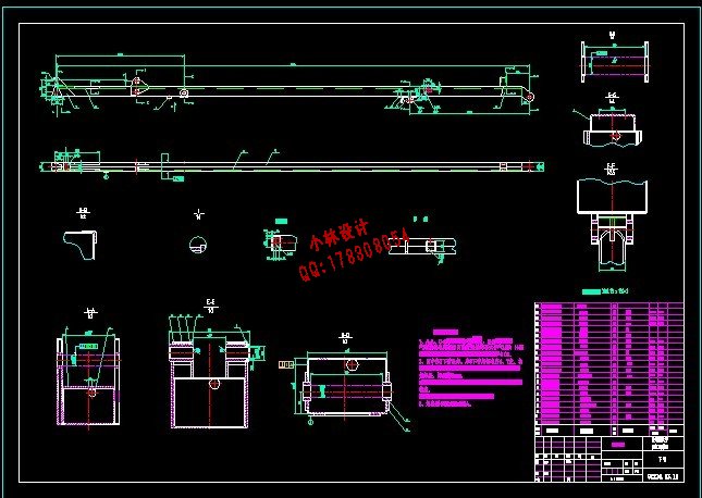
CAD版本图纸,共3张:
一、设计题目:
高空作业车工作臂结构设计及有限元分析
二、设计任务要求及主要原始资料:
设计任务要求:
工作臂总体设计(总装图一张),上、下臂结构设计(零件图两张),上、下臂铰点位置确定(优化),上臂或下臂有限元分析及改进、有限元分析结果的比较。
原始数据如下表
高空作业车主要技术参数
高空作业车工作臂结构设计及有限元分析
[摘 要]:高空作业车是用来运送工作人员和工作装备到指定高度进行作业的特种车辆。本文主要以“GKZ型高空作业车”上、下臂结构为研究对象,对上、下臂进行结构设计和ANSYS有限元分析。本文主要阐述了根据高空作业车的最大作业高度12米,在满足作业高度的前提下,进行高空作业臂的结构设计:首先根据使用要求选择作业臂材料的类型;其次根据最大作业高度确定上、下臂的长度;再经过受力分析利用强度来确定臂的截面尺寸及油缸的铰接位置;再进行强度、刚度、稳定性的校核,查看作业臂的尺寸是否符合要求;利用PRO/E软件进行上、下臂实体建模,通过PRO/E软件的输出端口和ANSYS软件的输入端口,将实体模型导入ANSYS软件中。在ANSYS软件中,先定义工作臂的单元类型为实体单元“Solid Brick 8 node 45”;其材料属性定义为:弹性模量为2.1e11,泊松比为0.3,钢的密度为 。进行网格划分时,采用了ANSYS提供的最常用的网格划分控制工具“MeshTool”中的“SmartSize Controls”,网格划分的值越小得到的结果越好,但网格太细会占用大量的分析时间,造成资源浪费,由于上、下臂的尺寸较大,而厚度较小,为提高计算效率,在网格划分密度时,选取值为4。然后,施加均布载荷和约束,进行结构的强度和刚度分析,确定危险截面或危险点的应力分布及变形。根据有限元分析结果,找出结构设计中的不合理因素,提出改进方案,并对改进后的结构进行有限元分析,对两种分析结果进行比较。最后画出作业臂总装图及上、下臂零件图。
[关键词]:高空作业车;结构设计;有限元分析;ANSYS
Aerial vehicle arm of Aerial work platform structure
designand finite element analysis
[Abstract]:Aerial vehicle arm of Aerial work platform is a special vehicle which carries operators and tools to the aerial appoint place for work,In this paper, “GKZ high-altitude vehicles in the” upper and lower arm structure of the research object, right, under arms, structural design and Finite Element Analysis. This paper elaborated on the basis of aerial vehicle operations largest 16 meters high, to meet the high operating on the premise that for high-altitude operations arm of structural design : First choice under the requirements of the use of operating arm of the types of materials; Second, based on the height of the largest operations to determine the upper and lower arm length; After Analysis to determine the intensity of use of the arm section size and fuel tanks articulated position; further strength, stiffness, Stability of Verification, check the operating arm size whether it meets the requirements; PROE software using the upper and lower arm entity modeling, PROE software through the output ports and ANSYS input ports, Entity Model into ANSYS software. In ANSYS, first definition of the modules work arm type of entity unit "Solid Brick 8 node 45"; material properties : the definition of elastic modulus of 2.1 e11, the Poisson's ratio of 0.3, the density of steel. For mesh, ANSYS used for the most commonly used mesh control tool "MeshTool" of the "Smar tSize Controls, "mesh smaller the value the better the results. But mesh too small will occupy a great deal of analysis time, resulting in a waste of resources, since the upper and lower arm of a larger size. thickness and smaller, to increase the efficiency of the computation, the mesh density, the selected value of four. Then, impose uniform loads and constraints, structural strength and rigidity, identify hazardous or dangerous section the stress distribution and deformation. According to the finite element analysis, structural design to identify the irrational factors that improvement program also improved the structure of finite element analysis, the analysis of both results. Finally paint operations arm assembly diagram and the upper and lower parts arm map.
[Keywords]:Aerial vehicle arm of Aerial work platform;Structural design;Finite element analysis;ANSYS
目 录
第一章 绪 论 4
1.1高空作业车的概况及其发展方向 4
1.2高空作业车组成 5
1.2.1 工作机构 5
1.2.2 金属结构 5
1.2.3 动力装置 6
1.2.4 控制系统 6
1.3 GKZ型高空作业车的概况 6
1.3.1整机结构简介 6
1.3.2高空作业臂 7
1.3.3 作业车作业状态主要技术参数 8
1.4 课题的提出 8
1.5 本课题所要研究的具体任务 9
1.6 本课题研究的意义 9
第二章 高空作业车的结构设计 10
2.1 材料的选择 10
2.2 计算上、下臂的长度 11
2.3 确定油缸铰点的位置 12
2.3.1 确定上臂油缸铰点的位置 12
2.3.2 确定下臂油缸铰点的位置 13
2.4 上臂截面尺寸的确定 13
2.4.1 对上臂进行受力分析 13
2.4.2 计算上臂截面尺寸 14
2.4.3 对上臂进行强度效核 16
2.5 下臂截面尺寸的确定 18
2.5.1 对下臂进行受力分析 18
2.5.2 计算下臂的截面尺寸 21
2.5.3 对下臂进行正应力效核 22
第三章 高空作业臂有限元分析 25
3.1 概述 25
3.2 载荷条件及分析工况说明 26
3.2.1 载荷条件 26
3.2.2 分析工况 26
3.3 上臂的有限元分析 27
3.3.1上臂的实体建模 27
3.3.2 有限元分析 28
3.4 下臂的有限元分析 32
3.4.1下臂的实体建模 32
3.4.2 有限元分析 32
第四章 总 结 36
致 谢 39
参考文献 40
|