|
设计简介 |
设计描述:
文档包括:
Word说明书1份,共26页,约14000字
CAD版本图纸,共12张
目录
1 前言 1
2 组合机床总体设计 3
2.1 总体方案论证 3
2.1.1 加工对象工艺性的分析 3
2.1.2 机床配置型式的选择 3
2.1.3 定位基准的选择 3
2.1.4 滑台型式的选择 3
2.2 切削用量的确定及刀具选择 4
2.2.1 切削用量选择 4
2.2.2 切削力、切削扭矩及切削功率的计算 4
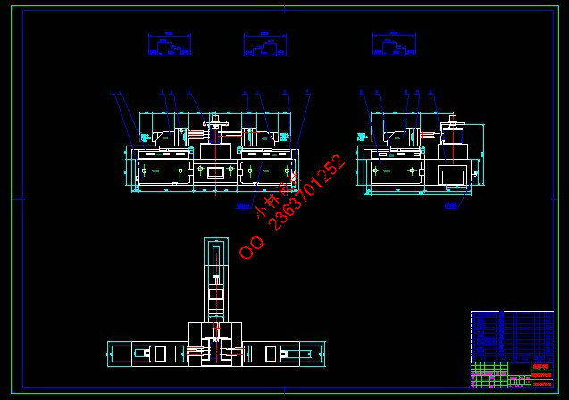
2.3 组合机床总体设计—三图一卡 5
2.3.1 被加工零件工序图 5
2.3.2 加工示意图 6
2.3.3 机床尺寸联系总图 8
2.3.4 机床生产率计算卡 10
2.3.4.1 理想生产率 10
2.3.4.2 实际生产率 11
2.3.4.3 机床负荷率 12
3 组合机床主轴箱设计 13
3.1 主轴箱原始依据图的绘制 13
3.2 主轴结构型式的选择和动力计算 14
3.3 主轴箱传动设计 14
3.3.1 主轴箱传动路线的拟订 15
3.3.2 根据原始依据图对坐标尺寸的计算 15
3.3.3 传动轴位置及齿轮齿数的确定 15
3.3.4 传动轴直径的确定 17
3.4 主轴箱坐标计算、坐标检查图的绘制 17
3.5 轴、齿轮、轴承、键的校核 19
3.5.1 轴的校核 20
3.5.2 齿轮的校核 20
3.5.3 轴承的寿命校核 22
3.5.4 键的强度计算 23
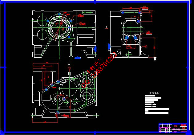
3.6 主轴箱前、后盖及箱体设计 23
3.7 附件的选择 23
4 结论 25
参考文献 26
致 谢 27
附 录 28
ZS175柴油机机体三面钻削组合机床
总体及右主轴箱设计
摘 要:组合机床是用按系列化标准化设计的通用部件和按被加工零件的形状及加工工艺要求设计的专用部件组成的专用机床。本课题设计了一台用于ZS175柴油机机体三面钻孔的组合机床。机床采用卧式三面加工的方案,加工和装配的工艺性好,零件装夹方便。设计内容主要分为总体设计和右主轴箱设计两部分。总体设计包括机床配置型式的确定、结构方案的选择以及“三图一卡”的绘制。主轴箱是组合机床的重要部件之一,按专用要求进行设计,由通用零件组成,靠夹具的导向装置来保证孔的加工位置精度。其主要作用是,根据被加工零件的加工要求,安排各主轴位置,并将动力和运动由电机或动力部件传给各主轴,使之得到要求的转速和转向。主轴箱设计包括主轴箱原始依据图的绘制,主轴结构型式的选择和动力计算,主轴箱传动系统的设计与计算,主轴箱坐标计算、坐标检查图的绘制,轴、齿轮、轴承、键的校核,主轴箱前、后盖及箱体设计。本组合机床运转平稳,结构简单,工作可靠,装卸方便,提高了工作效率,达到了设计要求。
关键词:组合机床;钻削;主轴
Design of the General and Right Headstock of Modular Machine Tool for drilling Holes on Three-Side of the body of ZS175 Diesel Engine
Abstract: Machine is designed according to the standardization and serialization of generic components and parts are processed according to the shape and design of process-specific components of a dedicated machine. A Modular machine tool was designed for the ZS175 diesel engine with three-side drilling holes. Three horizontal machine used for processing program, processing and assembly process is good, spare parts to facilitate clamping. The focal point of this topic could be divided into two parts: the general design and the right headstock design. The general design includes the confirmation of the modular machine tool, the selecting of the structure type and the completing of the technological drawing of the parts to be manufactured, the general drawing of modular machine tool, drawing of cutter display and the efficiency card of manufacturing. Combination of machine tool spindle box is one of the important parts, according to special requirements of design, from the common parts of the fixture on the guiding device to ensure the accuracy of hole location processing. Its main role is to be processed in accordance with the processing requirements of parts, arrangement of the spindle position, and power and movement by electrical or power components to the spindle, so that it can be the requirements of speed and steering. Spindle box spindle box design includes mapping the original basis, the choice of spindle structure and dynamics, the spindle box drive system design and calculation, spindle box coordinates, the mapping coordinates inspections, shafts, gears, bearings, the school bond nuclear, spindle box before the design of the rear cover and cabinet. Combination of the smooth functioning of the machine, simple structure, reliable work, loading and unloading convenience, increased efficiency, to achieve the design requirements.
Key words: Modular Machine Tool; Drilling; Head stock
|