|
设计简介 |
设计描述:
文档包括:
Word说明书1份,共33页,约18000字
CAD版本图纸,共13张
目 录
1 前言 1
2 组合机床总体设计 3
2.1 总体方案论证 3
2.1.1 工艺路线的确立 3
2.1.2 机床配置型式的选择 3
2.1.3 定位基准的选择 4
2.1.4 滑台型式的选择 4
2.2 切削用量的确定及刀具选择 4
2.2.1 选择切削用量 4
2.2.2切削力、切削扭矩及切削功率的计算 6
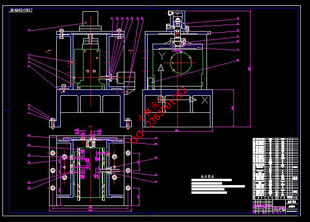
2.3 组合机床总体设计—三图一卡 8
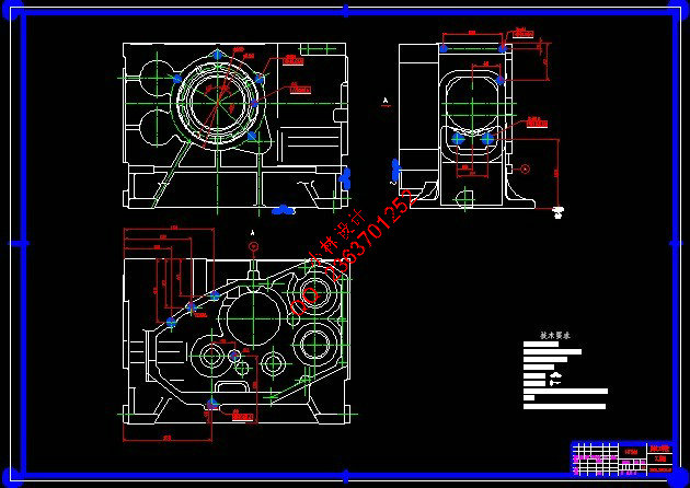
2.3.1 被加工零件工序图 8
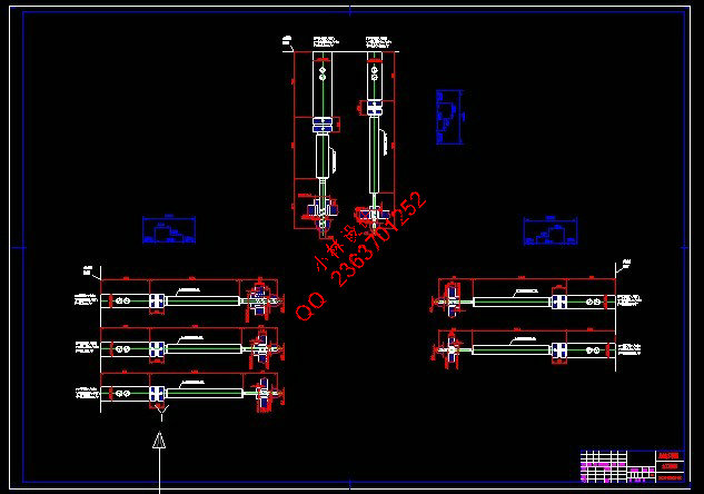
2.3.2 加工示意图 8
2.3.3机床尺寸联系总图 12
2.3.4 机床生产率计算卡 14
3 夹具设计 17
3.1 概述 17
3.1.1 零件的工艺性分析 17
3.1.2 夹具设计的基本要求 17
3.1.3 夹具总体结构构思 18
3.2 定位方案的确定 18
3.2.1 定位方案论证 18
3.2.2 定位基准的选择 18
3.3 误差分析 19
3.3.1 影响加工精度的因素 19
3.3.2 保证加工精度的条件 20
3.4.1夹紧装置的确定 21
3.4.2夹紧力的确定 22
3.4.3夹紧液压缸的选择 23
3.5 导向装置的选择 24
3.5.1钻套型式的选择和设计 24
3.5.2 钻模板的类型和设计 25
3.6 夹具体的确定 25
4 结论 27
参考文献 28
致 谢 29
附 录 30
ZS175柴油机机体三面钻削组合机床总体及夹具设计
摘 要:柴油机机体是大批量生产的零件,为了提高加工精度和生产效率,需要设计一种组合机床来改善柴油机机体的加工情况。
本课题设计了一台用于ZS175柴油机机体三面钻孔的组合机床。全文共有两部分,组合机床的总体设计和夹具设计。首先是总体设计,采用单工位三面钻孔组合机床,其中有加工对象工艺性的分析,机床总体布局的确定,定位基准的选择,滑台型式的选择,切削用量和刀具的选择,机床的总体设计。其次是夹具设计,通过对被加工零件的全面分析,在夹具设计过程中,采用后面、左面、下面三面定位, 左面和后面用定位销定位,下面用定位条定位。上面用液压缸夹紧,右面用液压缸辅助夹紧;夹具体为框架式结构,有良好的刚性,使夹具能长期保持可靠的精度和稳定性。
该组合机床不仅能保证加工精度,还能提高加工效率。整个机床布局合理,夹紧可靠,精度较高,使用操作方便,提高了工作效率,达到了设计要求。
关键词:组合机床;夹具;钻削
The General and Jig Design of The Modular Machine Tool for the three-side drilling on the ZS175 diesel engine body
Abstract: The engine body of diesel is made for large mass production, a modular machine tool is designed to improve the accuracy and efficiency of diesel production.
The topic is produced for designing a combined machine-tool to be used with three-side drilling holes on the ZS175 diesel engine body. The design was introduced of the general and jig of the combined machine-tool and the topic consists of two parts. The first part is general design, adopting the combined machine-tool with single location three-face drilling holes, processing of analysis of the object, the overall layout of the machine determined that the choice of location base, the choice of slider type, the choice of the amount of tools and cutting to complete the general design. The second part is the jig design, having analyzing the workpiece, In the design process of jig, the work piece has been located by three surfaces—behind, left and underside. A pin has been used on the behind and left. Orientation bars have been used on the underside. Using hydraulic cylinder to clamp the above and the right side; the jig-body utilize the frame structure, possess fine rigidity, causes the jig to maintain good long-term precision.
This combined machine-tool can ensure the precision and enhance processing efficiency. The laying out of the machine-tool is reasonable and the location of work piece is reliably. What’s more , the accuracy is high and operation is easy, which can enhance the working efficiency and meet with the design requirement well.
Key words:Modular machine tool; Jig; drilling.
|