|
设计简介 |
设计描述:
文档包括:
Word说明书1份,共35页,约17000字
CAD版本图纸,共12张
目录
1 前言 1
2 组合机床总体设计 3
2.1 总体方案论证 3
2.1.1 工艺路线的确定 3
2.1.2 机床总体布局的确定 3
2.1.3 滑台型式的选择 3
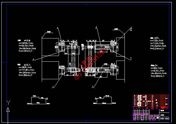
2.2 切削用量的确定及刀具选择 4
2.2.1 切削用量选择 4
2.2.2 切削力、切削扭矩及切削功率的计算 5
2.3 组合机床总体设计—三图一卡 6
2.3.1 被加工零件工序图 6
2.3.2 加工示意图 7
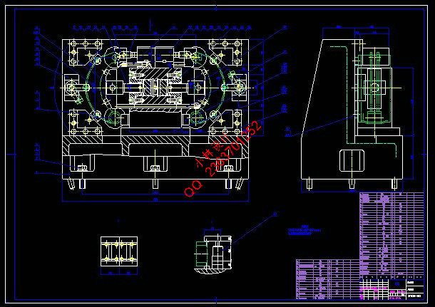
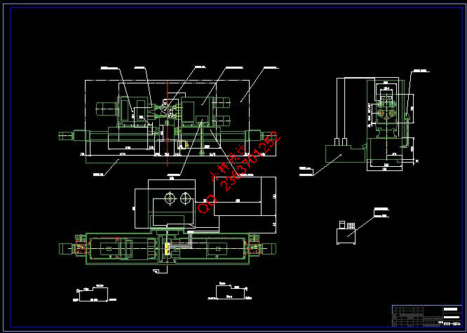
2.3.3 机床尺寸联系总图 10
2.3.4 机床生产率计算卡 14
3 组合机床夹具设计 18
3.1 夹具的设计要求与选型 18
3.1.1 夹具设计的基本要求 18
3.1.2 夹具的选型 18
3.1.3 夹具设计的步骤 19
3.2 定位方案的确定 19
3.2.1 零件的工艺性分析 19
3.2.2 定位方案确定 20
3.3 定位元件和夹紧元件的设计计算 22
3.3.1 定位元件的设计计算 22
3.4 夹紧方案的确定 24
3.4.1 夹紧装置的确定 24
3.4.2 夹紧方案论证 24
3.4.3 夹紧力的确定 25
3.5 液压驱动装置的设计计算 26
3.5.1 液压缸的设计与计算 26
3.5.2 活塞的设计选择 26
3.5.3 活塞杆的设计选择 26
3.5.4 导向套的设计选择 27
3.5.5 密封元件的设计选择 27
3.6 误差分析 27
3.7 校核加工精度 28
3.8 夹具体的设计 28
4 结论 30
致 谢 31
参考文献 32
附 录 33
双孔支架镗铰组合机床总体及夹具设计
摘要:随着生产的发展和专业化程度的提高,很多企业的产品产量越来越大,精度也越来越高。首先,加工时,同时参加工作的刀具少,限制了机床生产率的提高;其次,在加工多孔的工件时,需要对工件进行多次的定位和夹紧,使零件的加工精度和生产率降低;第三,因为在一台机床上总是加工一种工件,使通用机床的部件和机构造成冗余。因此,为了提高生产效率,满足加工要求,本课题设计了用于加工双筋蹄零件的镗铰组合机床之镗削主轴箱。根据被加工零件确定加工孔的数量、位置、切削用量及主轴类型,拟订了主轴箱的传动方式,应用最优化方法传递功率,削减振动,确定传动参数,设计轴的结构,进行如轴、轴承等相关零件的强度校核计算。通过以上设计,实现了两个双筋蹄零件一次加工完成,较好地达到了设计要求。
关键词:组合机床;镗床;夹具
The design of the modular machine tool for double rebar and feet parts boring and drilling
Abstract: With the development of industry and improvement of the specialization, the products output of enterprise, is growing, the precision is increased precise high. First, fewer tool in the work at the same time that limiting machine tool productivity; Secondly, it is needed to clamp and position many times in processing that reduce the accuracy and productivity; Third, parts and body of lead to machine tool will lead to redundant if process only one work in some machine tool. Therefore, to improve the machining efficiency and satisfy the processing requirements, the boring headstocks are designed which are used for the unit machine tool, which is used to roughly bore the holes of the double rebar and feet parts. Based on the processed accessory, the number, the position and the machining data of the holes and the form of the principal axis are determined; The driving way of the headstocks are drawn, the power is transmits by the methods of optimization, the driving parameter are determined, the structure of the principal axis are designed and the strength of the parts, such as the strength and the bears, are checked. Trough the design, the four holes of two parts can be finished at one time, and can fulfill the design requirements better.
Key words: unit machine tool; boring machine tool; headstock
|