|
设计简介 |
设计描述:
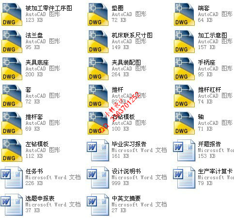
文档包括:
Word说明书1份,共43页,约20000字
CAD版本图纸,共16张
目 录
1前 言 1
1.1 本课题的意义 1
1.2 国内(外)发展概况及现状 1
1.3 课题由来及基本条件 3
1.4 课题设计思路 3
1.5 预期成果及实际价值 4
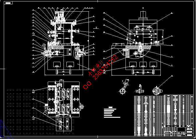
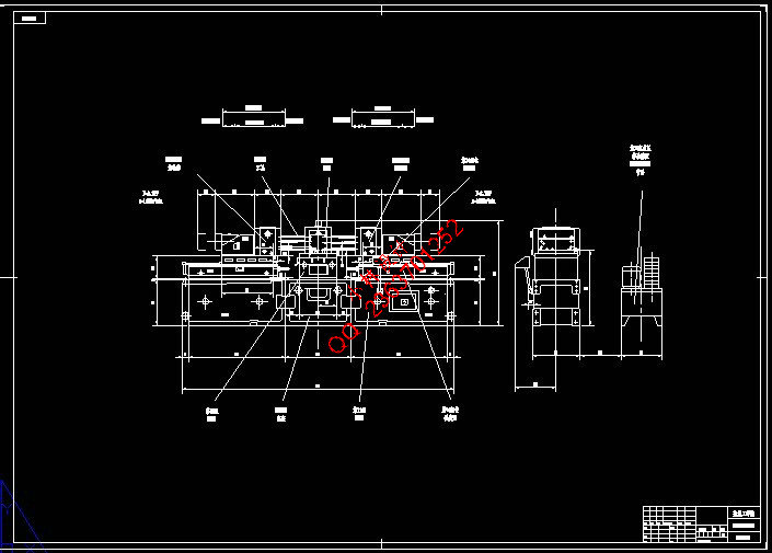
2组合机床总体设计 5
2.1 工艺方案的拟订 5
2.1.1 分析、研究被加工零件 5
2.1.2 组合机床总体方案论证 5
2.1.3 定位基准及夹压点的选择 6
2.2 详细设计计算 6
2.2.1 刀具的选择 6
2.2.2 切削用量的选择 6
2.2.3 计算切削力、切削扭矩、切削功率及刀具耐用度 7
2.2.4 确定主轴、尺寸、外伸尺寸 11
2.2.5 选择接杆 11
2.2.6 导向结构的选择 12
2.2.7 动力部件工作循环及行程的确定 12
2.3 通用部件的选择 13
2.3.1 机床配置型式 13
2.3.2 选用滑台型式 13
2.3.3 选液压滑台的型号 14
2.3.4 选动力箱型号 14
2.3.5 选择滑台侧底座 15
2.4 确定机床联系尺寸 15
2.4.1 机床装料高度的确定 15
2.4.2 夹具轮廓尺寸的确定 15
2.4.3 中间底座尺寸的确定 15
2.4.4主轴箱轮廓尺寸的确定 16
2.5 机床分组 16
2.6 机床生产率计算卡 17
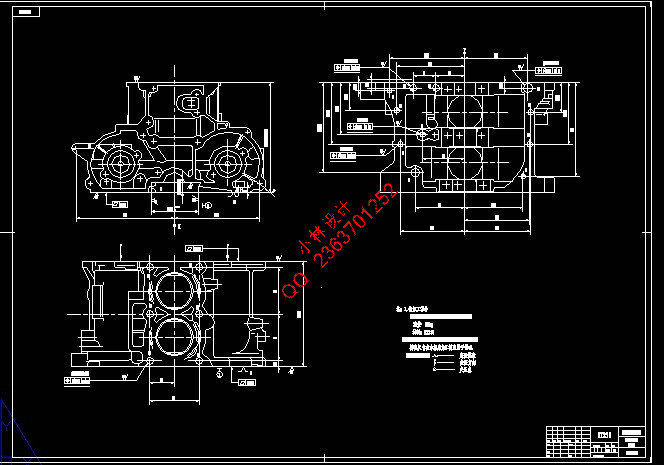
3 组合机床夹具设计 21
3.1 夹具设计的基本要求和步骤 21
3.1.1 夹具设计的基本要求 21
3.1.2 夹具设计的步骤 21
3.2 定位方案的确定 22
3.2.1 零件的工艺性分析 22
3.2.2 定位方案论证 23
3.3导向装置 24
3.4 夹紧方案的确定 26
3.4.1 夹紧装置的确定 26
3.4.2 夹紧方案论证 27
3.4.3 夹紧力的确定 28
3.4.4 液压缸的选择 29
3.5 误差分析 29
3.5.1 定位误差的分析 29
3.5.2 校核加工精度 31
3.6 夹具体的设计 31
4 结论 33
参 考 文 献 34
致 谢 36
附 件 清 单 37
双缸柴油机汽缸体钻削组合机床总体及夹具设计
摘要:柴油机汽缸体为大批量生产的零件,为了提高生产效率,满足被加工零件的精度要求及保证加工精度的稳定性,本课题设计了一台用于双缸柴油机汽缸体双面钻孔的组合机床。本文介绍了该组合机床总体设计和夹具设计的思路与内容。第一部分是总体设计,首先,进行了总体方案论证,采用单工位双面钻削组合机床,刀具选用高速钢麻花钻,并根据切削用量的选择,计算切削力、切削扭矩及切削功率,确定主轴直径、外伸尺寸、接杆型号,选择滑台、动力箱等通用部件,再确定动力部件的工作循环及工作行程,完成机床联系尺寸的制定。最后绘制了三图一卡。第二部分是夹具设计,经过对被加工零件的全面分析,定位方案采用三面定位,导向采用固定钻模板可换钻套导向,夹紧装置采用液压夹紧机构,直接夹压于工件上,反应快捷,夹压平稳可靠,夹具体为框架式结构,有良好的刚性,使夹具能长期保持可靠的精度和稳定性。该组合机床不仅能保证钻孔精度,还能提高加工效率,降低工人的劳动强度。设计的夹具定位可靠、夹压稳定、操作方便,达到了设计要求。
关键词:组合机床;钻孔;总体设计;夹具设计
The overall and jig design of the overall and jig the combined machine-tool for drilling the body of two-cylinder diesel
Abstract:The cylinder block of diesel is a product which nedds mass production. In order to prove the production efficiency,and meet the precision requeste of the components processed and the precision stability, this topic design a combined machine-tool to be used in the two-cylinder diesel engine with both sides drilling holes. It introduces the design of overall and jig of this combined machine-tool. The first part is overall design. First, it carries out the argumentation of the overall plan, adopte the combined machine-tool with single location double faces drilling, selecte the high-speed steel twist drill. According to the cutting parameters, it calculates the cutting force, the cutting torque and the cutting power, determined spindle diameter, the extend size and the link-pole model, chose sliding table, the power box and so on, then determine the operating cycle and the stroke of the power part, formulate the relation size of the machine-tool. Finally, it figures out the productivity which satisfies the request. The second part is the jig design, after analyse the workpiece, the location plan adopte three-face location; the guiding equipment used the fixed drill plate with replaceable drill bush; the clamp uses the hydraulic pressure device, it directly presses on the workpiece, which responds quickly, fixes steadily and reliably; the jig-body utilize the frame structure, possess fine rigidity, causes the jig to maintain good long-term precision. This combined machine-tool not only guarante the drill hole precision, but also enhance the processing efficiency, reduce workers' labor intensity. The jig orients reliably, clamps stably, operates easily, and meets it the design request well.
Key words:Combined machine-tool; Drill hole; Overall design;Jig design
|