|
设计描述:
文档包括:
Word说明书1份,共35页,约16000字
CAD版本图纸,共12张
目 录
1前言 1
2组合机床总体设计 3
2.1总体方案论证 3
2.1.1工艺路线的确立 3
2.1.2确定机床配置型式及结构方案 3
2.1.3定位基准的选择 3
2.1.4滑台型式的选择 4
2.2 确定切削用量及选择刀具 4
2.2.1选择切削用量 4
2.2.2计算切削力、切削扭矩及切削功率 5
2.3 组合机床总体设计—三图一卡 6
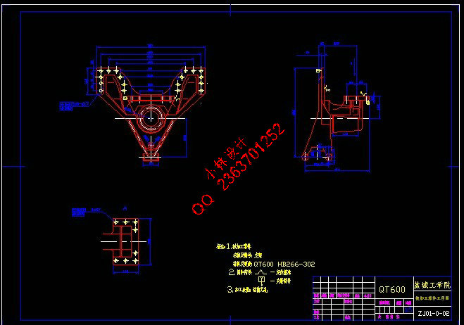
2.3.1被加工零件工序图 6
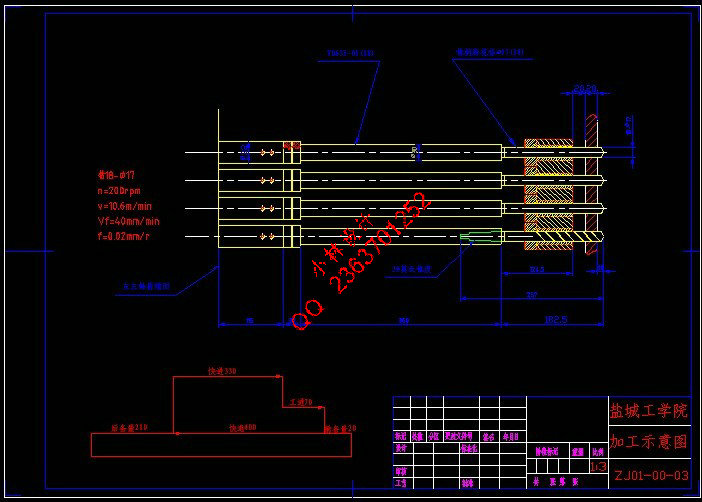
2.3.2加工示意图 6
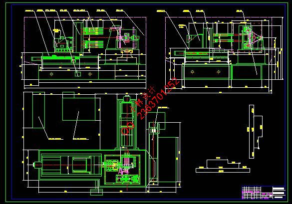
2.3.3机床联系尺寸图 8
2.3.4机床生产率计算卡 10
3 组合机床左主轴箱设计 13
3.1绘制左主轴箱设计原始依据图 13
3.2主轴结构型式的选择及动力计算 14
3.2.1主轴结构型式的选择 14
3.2.2主轴直径和齿轮模数的初步确定 14
3.2.3主轴箱动力计算 14
3.3主轴箱传动系统的设计与计算 15
3.3.1根据原始依据图计算驱动轴、主轴的坐标尺寸 15
3.3.2拟订主轴箱传动路线 15
3.3.3传动轴的位置和转速及齿轮齿数 16
3.3.4手柄轴的设置和主轴箱的润滑 20
3.4主轴箱中传动轴坐标的计算及坐标检查图的绘制 20
3.4.1传动轴坐标的计算 20
3.4.2坐标检查图的绘制 23
3.5传动轴直径的确定和轴强度的校核 23
3.5.1轴径的确定 23
3.5.2轴的校核 24
3.6齿轮校核计算 24
3.7轴承的选择与校核 25
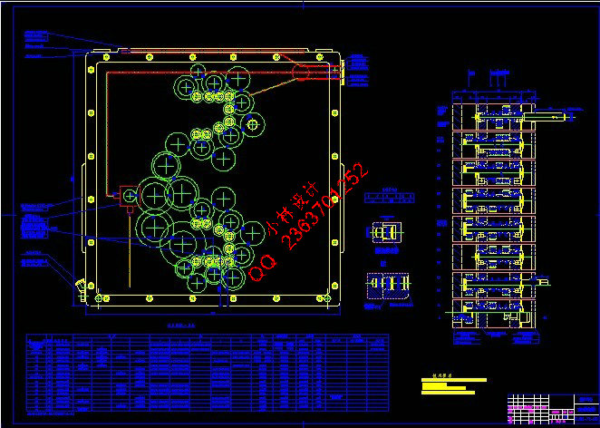
3.8主轴箱的设计 28
4结论 29
参 考 文 献 30
致 谢 31
附 录 32
“Y”形支架双面钻机床总体设计 及左主轴箱设计
摘要:卧式支架双面钻机床加工的是支架零件。主要钻削加工支架上的18-φ17和8-φ17孔。在分析加工工件的特点的基础上,按组合机床的设计方法和步骤,进行了组合机床的总体设计,绘制了被加工零件的工序图、加工示意图、机床联系尺寸图和生产率计算卡。采用标准主轴,并选用标准刀具,同时使得工序尽量集中,能够实现工件在一次装夹时多孔同时加工,这样有利于保证各面和各孔相互间的位置精度要求。在此基础上,绘制了左主轴箱设计的原始依据图,拟订了主轴箱的传动路线,应用最优化方法布置齿轮。确定传动参数,绘制了主轴箱装配图、箱体坐标检查图、前盖及后盖的补充加工图,进行了轴、齿轮等零件的强度校核。本设计较好的满足了生产实践的需要,大大提高了工作效率。
关键词:左主轴箱;组合机床;双面钻孔
The“Y”Type for the bracket for Design of Two-side Drilling machine and Design of Left spindle box
Abstract: The“Y”Type for the bracket of two-side Drilling machine manufactures the bracket mainly. The machine makes 26 holes with dills and the drilled diameter is 17mm. On the base of the characteristics of the analysis’s process , the methods and steps of the design of the modular machine tool, the designing system was made. By the process of drawing ,the schematic diagram of machining ,the relationship of the machine size and the card of the productivity were drawn. With this kind of machining jig, parts do not need be loaded for multiple times, and most holes could be drilled out at the same time. In this way, the surfaces and holes can meet high precision of location. Then the primitive chart for the design of the left-side spindle box was given out. The transmission route was confirmed and the transmission parameter was made. The assembly diagram of the spindle box was drawn. After arranging the gears ,we used the optimized design. The supplement processing diagram of the front side and behind side plate were also made. The intensity of the axises and gears was checked.This design met production practice needs better and the controlling precision was wholly improved.his
Keywords:Left spindle box; Modular Machine Tool; two-side Drilling.
|