|
设计简介 |
设计描述:
文档包括:
Word说明书1份,共43页,约18000字
CAD版本图纸,共13张
目 录
1 前言 1
2 组合机床总体设计 3
2.1 总体方案论证 3
2.1.1加工对象工艺性的分析 3
2.1.2 机床配置型式的选择 3
2.1.3 定位基准的选择 4
2.1.4 滑台型式的选择 4
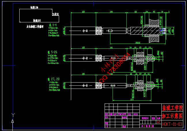
2.2 切削用量的确定及刀具选择 4
2.2.1 切削用量选择 4
2.2.2 计算切削力、切削扭矩及切削功率 6
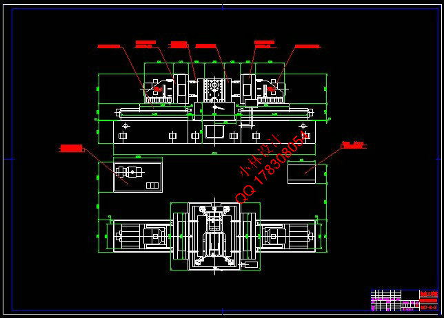
2.3 组合机床总体设计—三图一卡 9
2.3.1 被加工零件工序图 9
2.3.2 加工示意图 10
2.3.3机床尺寸联系总图 13
2.3.4 机床生产率计算卡 16
3 组合机床左主轴箱设计 18
3.1 绘制多轴箱设计原始依据图 18
3.2 主轴结构型式的选择及动力计算 19
3.2.1 主轴型式的选择 19
3.2.2 主轴直径和齿轮模数的初步确定 19
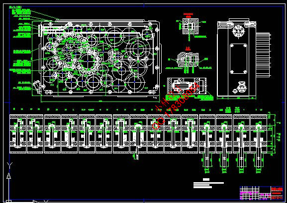
3.3 左主轴箱的传动设计和计算 20
3.4 传动系统设计 20
3.4.1 拟定传动路线 20
3.4.2 确定各轴间传动比 22
3.4.3 确定各轴齿轮齿数及传动轴位置 24
3.4.4 各传动轴直径的确定 26
3.5 左主轴箱坐标计算、绘制坐标检查图 26
3.5.1 计算传动轴的坐标 26
3.5.2 绘制坐标检查图 28
3.6 轴、齿轮的校核 29
3.6.1 齿轮的校核 29
3.6.2轴的校核 31
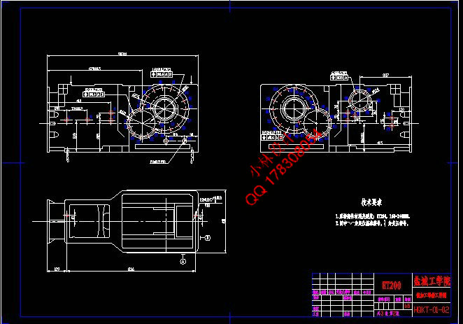
4 左主轴箱体及其附件的选择设计 35
4.1左主轴箱的选择设计 35
4.2 左主轴箱上的附件材料的设计 35
5.结论 36
致 谢 37
参考文献 38
附 录 39
后桥壳体双面钻组合机床总体及左主轴箱设计
摘 要:后桥壳体是需要大量生产的零件。为了提高加工精度和生产效率,需要设计组合机床来改善加工情况。本课题设计的是后桥壳体双面钻组合机床。该组合机床设计包括总体设计和部件设计两部分。总体设计包括机床配置型式的确定、结构方案的选择以及“三图一卡”的绘制。部件设计为左主轴箱设计,其中主轴箱设计包括绘制主轴箱设计原始依据图、确定主轴和齿轮、完成动力计算、设计传动系统。主轴箱根据变速箱体所需要加工孔的数量、位置来确定切削用量和主轴类型,采用1000mm×630mm的通用主轴箱。同时借助钻套引导麻花钻从而保证被加工孔的位置。设计过程中尽量使用了标准零部件,设计出的组合机床结构简单,操作方便,加工精度高,减轻了劳动强度,提高了加工效率,具有较好的经济性。
关键词:后桥壳体;钻孔;组合机床;主轴箱
Design of General and Left Headstock of Modular Machine Tool for Drilling Holes on Two-Side of rear axle shaft housing
Abstract: The rear axle shaft housing is a product which needs massive production. In order to improve the precision and the production efficiency, it is needed to design a high effective modular machine tool to make. This task is to design the general scheme and left headstock of modular machine tool for drilling holes on two-side of rear axle shaft housing. The design of modular machine tool includes the system design and the part design. The system design includes the definition of the modular machine tool, the selection of the structure plan and the completing of the technological drawings of the part which need to be manufactured, the general drawing of modular machine tool, drawings of cutter display and the efficiency card of manufacture. The part design includes headstock design, the headstock design includes drawing the primitive basic chart for the gear box, determing the spindle and the gears, completing the power computation, designing the transmission system, drawing the gear box assembly drawing and the part processing charts. The headstock is designed by the quantity, the location of the holes which are needed to be processed. The headstock has been selected 1000mm×630mm as the general body. The headstock uses the standard one, with the aid of drill bush to guide the twist drill and guarantee the precision of processed hole. During the design process, we must use standard component as much as possible to design the modular machine tool in order to simplifying the structure. The modular machine tool is easy to be operated, has high machining precision and can reduce the working intensity, enhance the machining efficiency and had the very good efficiency.
Keywords: rear axle shaft housing; Drill hole; Modular machine tool; Headstock.
|