|
设计描述:
文档包括:
word说明书一份,共39页,约12000字
CAD版本图纸,共5张
摘 要
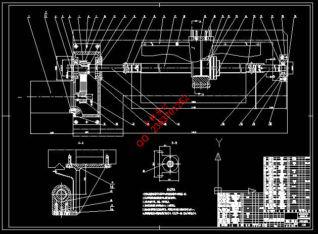
目前,我国数控系统和数控车床正处于由研究开发阶段向推广应用阶段过渡的关键时刻,而 125专用仪表数控车床是常用的数控车床之一。而 125专用仪表数控车床的进给传动机构是该型车床的关键部件之一。本设计即根据 125专用仪表数控车床技术规格和主要机构对横向和纵向进给机构进行设计。在设计的时候具体进行了详细的各部件的选型和计算,比如:机床功率和电动机选用,滚珠丝杠副选用与计算校核,方案设计即提出纵向和横向进给机构的设计方案,进行有关轴和齿轮强度、刚度校核,进行相关参数选择以及必要的参数校核计算等。
关键词:仪表车床、数控、传动系统
Abstract
At present, our country CNC system and CNC lathe is in by the research development phase to the popularization and application of key transitional stage moments, but 125 special instrument used CNC lathe is one of the CNC lathe. And 125 special instrument CNC lathes in transmission mechanism of this type of lathe is one of the key components. This design is 125 special instrument according to technical specifications and CNC lathe of major institutions horizontal and vertical lathe to carry on the design. In the design of the detailed specific selection and calculation of various components, such as: machine tool power and motor selection, ball screw vice selection and calculation checking, plan design will give longitudinal and transverse lathe, the design of gear on axis and the strength, stiffness checking related parameters selection, and the necessary parameters such as check calculation.
Keywords: Instrument lathe、CNC、drive system
目 录
摘 要 I
Abstract II
第1章 绪论 1
1.1 本课题研究的目的与意义 1
1.2 专用仪表数控机床简介 1
1.3 国内外仪表数控车床的发展状况 3
第2章 总体设计方案 4
2.1 专用仪表数控车床的工作原理 4
2.2 专用仪表数控车床进给运动的设计方案 5
第3章 进给系统的设计与计算 7
3.1 纵向进给系统的设计与计算 7
3.1.1 纵向进给系统设计 7
3.1.2 切削力计算 8
3.1.3 滚珠丝杠设计计算 10
3.1.4 选择步进电机的有关计算 13
3.2 横向进给系统设计与计算 15
3.2.1 横向进给系统的设计 15
3.2.2 切削力计算 16
3.2.3 滚珠丝杠设计计算 17
3.2.4 选择伺服电机的有关计算 20
第4章 进给系统的结构设计 23
4.1 床身和导轨 23
4.2 滚珠丝杠螺母副的设计 26
4.2.1 滚珠丝杠螺母副的形式 26
4.2.2 滚珠丝杠螺母副的计算 28
结 论 33
致 谢 34
参考文献 35
CONTENTS
Abstract I
Abstract II
Chapter 1 Introduction 1
1.1 This subject is the purpose of the research and meaning 1
1.2 Special instruments nc machine tools profile 1
1.3 Instruments both at home and abroad the development conditions of the CNC lathe 3
Chapter 2 The overall design scheme 4
2.1 Special instruments numerical control lathe principle of work 4
2.2 Special instruments numerical control lathe feed movement design scheme 5
Chapter 3 In the design of the system and calculated 7
3.1 The longitudinal into to the design of the system and calculated 7
3.1.1 In system design longitudinal 7
3.1.2 Cutting force calculation 8
3.1.3 Cutting force calculation 10
3.1.4 Choose the step motor relevant calculation 13
3.2 Traverse system design and calculation 15
3.2.1 Traverse the design of the system 15
3.2.2 Cutting force calculation 16
3.2.3 Ball screw design calculation 17
3.2.4 Choose the step motor relevant calculation 20
Chapter 4 The design of the structure of the system 23
4.1 Lathe bed and guide rail 23
4.2 Ball screw nut pair of design 26
4.2.1 Ball screw nut pair of form 26
4.2.2 Ball screw nut pair of computation 28
Conclusion 33
Thanks 34
References 35
|