|
设计描述:
文档包括:
Word版设计说明书1份,共42页,约13000字
外文翻译一份
CAD版本图纸,共9张
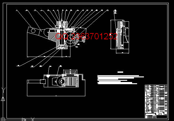
汽车自动调整臂的三维设计及预装配设计
摘 要
汽车自动调整臂(简称调整臂——ASA)是汽车制动系统的必备结构之一。传统的汽车自动调整臂结构复杂使用者不便操作。而本次设计的自动调整臂在结构上做了相应的调整,使得结构相对简单,而且安装高度可调,更便于安装。
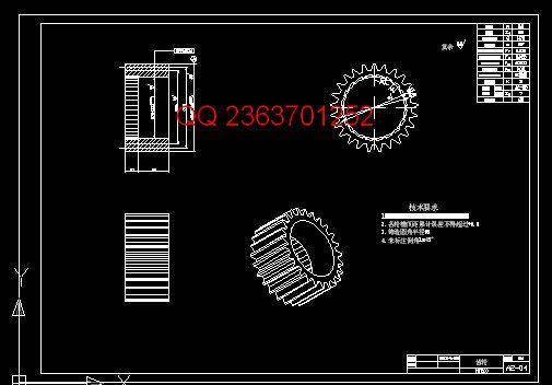
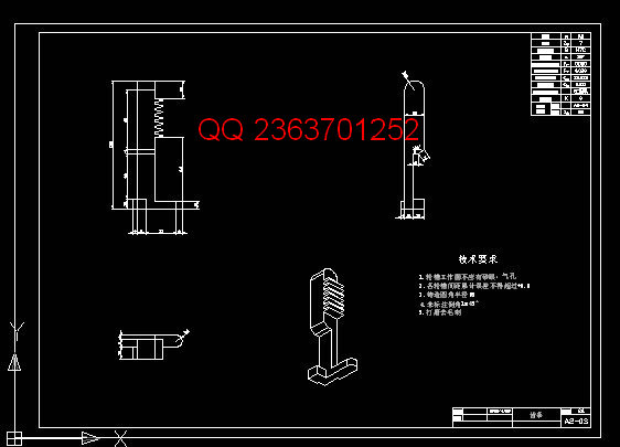
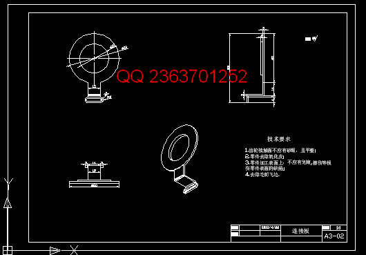
本结构是应用在汽车制动系统上,利用齿条和齿轮的单向可传动控制蜗轮转动以控制凸轮轴的旋转角度。主要零部件有:蜗轮蜗杆配合,齿条齿轮配合,以及单向离合结构。通过其配合来实现对凸轮轴的调整,使得制动间隙保持在恒定最优间隙。
本文对制动调整臂的开发原理,具体特点和使用方法做了相应介绍。
关键词:自动调整臂;结构;原理
3D design and pre-assembled design of the car automatically adjusts the arm
Abstract
Car adjustment arm (referred to as the adjustment arm - ASA) is one of the essential structure of the automotive braking systems. The traditional automotive automatically adjust the arm structure complex user inconvenience. The design of the automatic adjustment arm to do the appropriate adjustments in the structure, the structure is relatively simple, and the installation height adjustable, easy to install.
The present structure is applied to the vehicle brake system, the unidirectional transmission control a worm wheel rotational angle of rotation of the camshaft to control the use of a rack and pinion. The main components are: worm with rack and pinion with one-way clutch structure. With the camshaft adjustment, so that the brake clearance is maintained at a constant optimum gap.
Corresponding development principles, specific characteristics and use of the brake adjustment arm.
Key Words: Automatic Slack Adjuster; Structure;Principle
目 录
1 绪论 1
1.1 开发背景 1
1.2 结构设计的意义 4
1.3 开发者的主要工作 5
1.4 论文的组织结构 6
2 相关技术介绍 7
2.1 自动调整臂介绍 7
2.1.1自动调整臂简介 7
2.1.2自动调整臂特点 7
2.1.3自动调整臂的结构 8
2.2 自动调整臂工作原理介绍 8
3 自动调整臂的设计和实现 9
3.1 自动调整臂设计 10
3.1.1 自动调整臂设计任务 10
3.1.2 蜗轮蜗杆配合 10
3.1.3 齿轮齿条配合 15
3.1.3 单向离合器结构设计 18
3.1.4 臂体设计 19
3.2 自动调整臂装配 20
3.2.1 调整臂内部结构装配 20
3.2.2 调整臂总体结构装配图 21
3.3 调整臂的安装 21
3.3.1 基本传动说明 21
3.3.2 自动调整臂安装说明 25
4 校核 28
4.1 校核计划及执行情况 28
4.2 核心零件校核 28
4.2.1 单向离合器弹簧校核 28
4.2.2 轴承校核 29
4.2.3 蜗杆设计校核 29
5 建模 31
6 结论 33
7 体会 34
参考文献 35
致 谢 36
毕业设计(论文)知识产权声明 37
毕业设计(论文)独创性声明 38
|